iRiser Family User Guide

Version 3.8
November 2025
Copyright
Copyright© SANBlaze Technology, Inc., 2025. All Rights Reserved.
Contact Information:
SANBlaze Technology, Inc.\
One Monarch Drive\
Suite 204\
Littleton, Ma (USA) 01460\
1-978-679-1400
The information in this document is subject to change without notice and should not be construed as a commitment by SANBlaze Technology, Inc. SANBlaze Technology, Inc. assumes no responsibility for any errors that may appear in this document.
The software, if any, described in this document is furnished under a license and may be used or copied only in accordance with the terms of such license. SANBlaze Technology, Inc. and its affiliated companies assume no responsibility for the use or reliability of software or equipment not supplied by SANBlaze.
The following are trademarks of SANBlaze Technology, Inc.: SANBlaze™, Certified by SANBlaze™, VirtuaLUN™, VLUN™, iRiser™, the slogan We Test NVMe over Everything™, and the SANBlaze logo. All other trademarks and registered trademarks are the property of their respective holders.
SANBlaze holds multiple patents on its technology. Visit <https://www.sanblaze.com/patents for more information.
For Technical Support:
SANBlaze Help Center: <https://sanblaze.atlassian.net/servicedesk/customer/portals
Email: <support@sanblaze.com
Website: <https://www.sanblaze.com/contact-storage-testing-support
Table of Contents
Copyright
1 Introduction
2 Overview of the Installation and Configuration Steps
5 Updating and Configuring DT5/RM5/RM5+/RM6 Systems
5 Updating the System Software
7 Verifying the SBR Images
7 To get help for sb_flash
8 Display SBR image configuration
9 Verify that the Default SBR is Active
10 Getting Started with the GUI
11 iRiser GPIO Tab
15 GPIO Logging
16 iRiser Actions Tab
17 Starting from the top
17 GPIO Signal Table
18 User interaction with the GPIO Signal Table
22 Editing, adding and removing Actions using the GUI
22 Editing Actions
23 Deleting Actions
25 Adding Actions
26 Import and Export Configuration Files
28 iRiser Signals Tab
29 Selecting a Sequence
30 Starting a Sequence
32 iRiser Power tab
33 Creating Recordings
34 Recording Variables
36 iRiser recording status
37 Past recordings table
37 Refresh icon
37 A note on showing ongoing recordings
38 Viewing recordings
39 Live recordings
40 Recording summary
40 Current Selection window
41 Recorded Statistics View
42 Recorded data charts
43 Timeline view and navigation
44 Main chart
45 Getting Started with the CLI
45 Identifying Slots Containing an iRiser
45 Populating Slots with iRiser Hardware
46 Command Structure
47 Checking the Current State of Signals
48 Manually Setting or Clearing a Signal Control
48 How to Save, Store, and Share .cfg and .sh Files
49 Configuration Files
49 Find iRisers on PCIe
50 Using Read and Write Functions
50 Setting the GPIOs to Initial Default State
51 Writing the GPIO Registers as 32-bit Values
51 Setting I/O and GPIO Values from a File
53 Description of the GPIO Signals for iRiser
53 Showing the State of a Signal
53 show <signal\ -qq
54 Signals Available to Control
56 Setting GPIO Direction and Value
56 Signal Access by Name
56 Signal Access by Bit Location
57 Measuring Power
57 Backward-Compatible Power Measurement
57 Power Measurement via A-to-D and DMA-to-Host Memory
57 3.3V Margining
57 Show range of margining support
58 3.3V margining adjustment
58 Reset the margining level to the default value for the M.2 adapter
58 Power Monitoring
59 Starting a power recording
59 Stopping a power recording
60 Showing devices available for recording power
60 Displaying power recordings available
60 Displaying power recording content
61 Removing power recordings
61 Checking current status of power monitoring
62 Mirroring GPIO Bits
62 J8 - User Signal Connector
62 Mirroring Example
63 Unmirror Command
63 Monitoring GPIO Signals with Mirroring
64 Sequences and Actions
64 Examples of a Sequence of Actions
64 Example 1: Run Once and Stop Sequence
65 Example 2: Run until Stopped (loop)
65 Defining Actions from CLI Command
65 iriser -d <slot\ Edit Action
66 Initializing the Action Memory
66 Show Current Actions
67 Starting a Sequence
68 What happens while the Sequence is running?
68 Monitor Activity with Tracing
69 Monitoring Activity with sb_logger
70 Interactive Action Editing
70 Starting Point
72 Next Action Options
74 Additional notes on Adding new Actions
74 Showing Status of Sequences
77 Known issues
78 Appendix A: Programming the FPGA Code
79 Appendix B: FAQs
79 Question: Can I glitch or shut off PCIe lanes to my device to test its response to losing or noisy PCIe lanes?
79 Question: How are Sequence numbers assigned?
79 Question: Can I change Sequence numbers?
79 Question: I’m doing SRIS and SRNS testing on my machine. Will iRiser continue to function in a SRIS/SRNS configuration?
80 Question: What is the maximum number of iRiser cards you can support in a DT5, RM5, RM5+ or RM6 system?
80 Question: Can the FPGA FW code be updated in the field by the user as functionality is added?\
Introduction
The iRiser family of NVMe test tools from SANBlaze − consisting of iRiser5, iRiser5+ iRiser6 and iRiser6SE − provide precision control of PCIe/NVMe power and control signals while continuously monitoring the power of each device under test (DUT):
| iRiser Type | Description | SANBlaze System HW Compatibility | SANBlaze Minimum SW Support |
|---|---|---|---|
| iRiser5 | First iRiser for SBExpress-DT5 and RM5 systems | DT5, RM5 | 10.8 |
| PCIe Gen5 lane control and glitching capability | |||
| iRiser5+ | Adds support for SANBlaze 660 M.2 Adapter for DMA power reading and 3.3V margin capability | DT5, RM5 | 11.0-Build2 |
| iRiser6 | PCIe Gen6 iRiser with PCI lane control and glitching capability | RM5+, RM6 | 11.0-Build3 |
| Also supports SANBlaze 660 M.2 Adapter | |||
| iRiser6SE | Standard Edition PCIe Gen6 iRiser without PCI lane control or glitching capability | RM5+, RM6 | 11.0-Build7 |
| Also supports SANBlaze 660 M.2 Adapter |
Power sampling is possible at rates of up to ~1 Million samples per second (actual maximum rate is 961,538 samples/second), placing data in host memory with zero host CPU overhead.
A Sequence of events can be scheduled on each signal line with up to 10 nanoseconds (nS) precision, each with intervals from 10nS to hours. Simple or complex sequences can be defined and loaded to the iRiser from the host system.
This document describes how to install iRiser cards into the SBExpress-DT5, RM5, RM5+ or RM6 chassis, building and loading sequences to the iRiser and executing them, and provides examples of typical sequences.
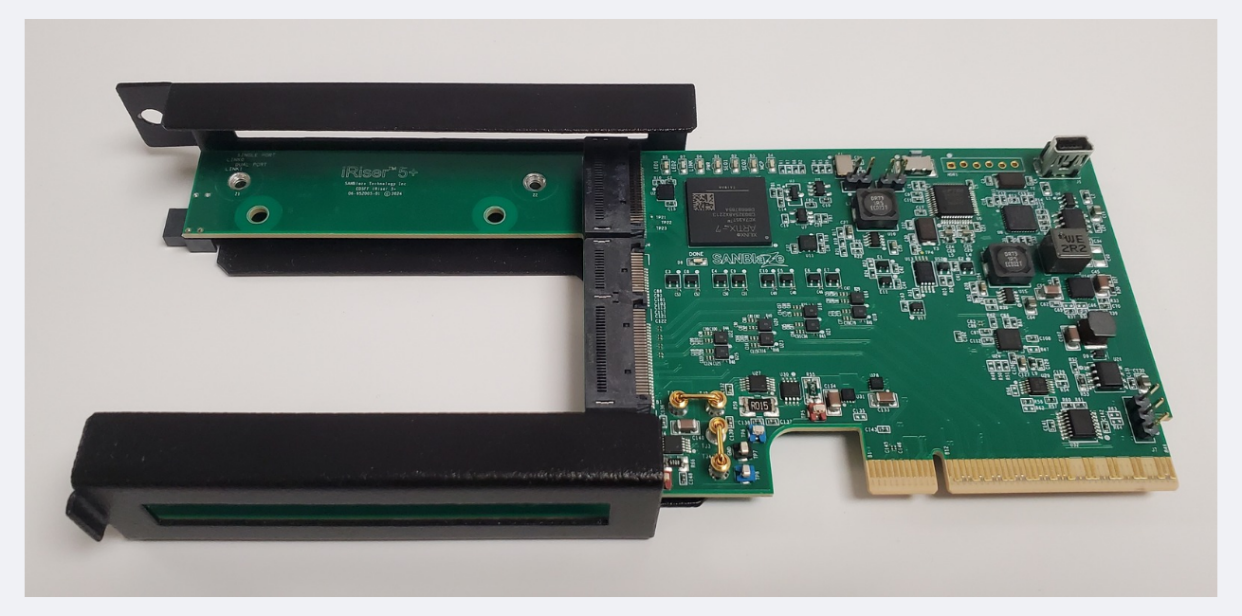
Figure 1: SANBlaze iRiser5+ Device
Note: iRiser 5+, iRiser6 and iRiser6SE devices can be paired with an optional 660 EDSFF-to-M.2 Adapter, which enables additional test capabilities for M.2 form-factor devices:
Adds ultra-precise power monitoring for M.2 3.3V and 1.8V power rails - with 20-bit precision (up to 78.125nV/bit)
Adds voltage margining capability of +/- 20% on M.2 3.3V power rail
Provides access to all other iRiser5+ / iRiser6 / iRiser6SE features for M.2 Devices, including:
Precise Control of Power, Data Path and Sideband Signals (CLKREQ, RESET, PERST, PLN/PLA)
PCIe lane glitching (available for iRiser5+ and iRiser6 only)
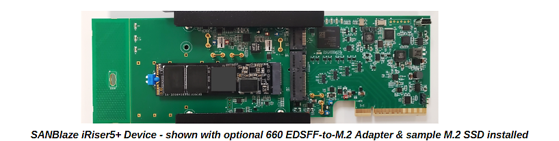
Figure 2: iRiser5+ device shown with optional 660 EDSFF-to-M.2 adapter and sample M.2 SSD installed
Overview of the Installation and Configuration Steps
The software upgrade requires the following items to proceed in the following order:
Update the system software to one of the minimum versions as indicated above.
Contact <sales@sanblaze.com for the latest software
(RM5 only) Verify that the Serial Boot Records (SBR) bridge firmware is upgraded to the latest, as shown in the [Verifying the SBR Images] section of the iRiser Family User Guide.
Power on the machine and verify the Software and SBR versions, using the following commands:
grep Version= /proc/vlun/config - to check the software version
sb_flash show - to check the SBR version
Power off the machine using the poweroff command.
Prepare to install the iRiser hardware into the RM5, DT5, RM5+ or RM6 chassis, noting the following:
For SBExpress-RM5:
Only iRiser5 and iRiser5+ devices can be installed in RM5
A maximum of [four] iRiser devices are supported and can be installed in slots 6, 7, 8 or 9
For SBExpress-DT5:
Only iRiser5 and iRiser5+ devices can be installed DT5
A maximum of [three] iRiser devices are supported and can be installed in slots 0, 1, or 2
For SBExpress-RM5+ or RM6:
Only iRiser6 and iRiser6SE devices can be installed in RM5+
Up to 16 iRiser devices are supported
Install the iRiser into the appropriate RM5, DT5 or RM5+ chassis. Refer to the SB-Express Installation Guides for details.
Power on the RM5, DT5, RM5+ or RM6.
Verify the correct operation of the iRiser hardware, using the following command:
- **lspci \|grep SANBlaze**
[In RM5 or DT5 only]
iRiser5 is Device 2015, revision d1 or higher
iRiser5+ is Device 2035, revision fe or higher
DT5 Motherboard is Device 2004
RM5 Motherboard is Device 2005
For example:
 **lspci \|grep SANBlaze**
    20:00.0 Signal processing management: SANBlaze Technology, Inc. Device 2004 (rev af)
    **\^ DT5**
    22:00.0 Signal processing management: SANBlaze Technology, Inc. Device 2015 (rev d1)
    **\^ iRiser5**
    23:00.0 Signal processing management: SANBlaze Technology, Inc. Device 2035 (rev fe)
    **\^ iRiser5+**
[In RM5+ or RM6 only]
iRiser6 is Device 2016, revision b2 or higher
iRiser6SE is Device 2026, revision e4 or higher
RM5+ Motherboard (MI5) is Device 2045, revision 6e or higher
RM6 Motherboard (MI6) is Device 2046, revision 6e or higher
For example:
 **lspci \|grep SANBlaze**
    31:00.0 Signal processing management: SANBlaze Technology, Inc. Device 2026 (rev e4)
    **\^ iRiser6SE**\
    4b:00.0 Signal processing management: SANBlaze Technology, Inc. Device 2046 (rev 6e)
    **\^ RM6**
Note
If a 660 M.2 Adapter is installed within any iRiser5+ / iRiser6 / iRiser6SE device being configured, the user must enable the adapter using the following command:
sb_i2c2 -d <slot\ -f 3V3M2 -w 1
where: <slot\ is the slot number of the iRiser5+ / iRiser6 / iRiser6SE device installed
This completes the iRiser installation.
If it becomes necessary to reset an iRiser device back to the factory default state, use the init command:
iriser -d \<slot\ init
After the init command is used, the drive under test should re-link on PCIe and power up ready.
Updating and Configuring DT5/RM5/RM5+/RM6 Systems
This section describes how to update and configure DT5/RM5/RM5+/RM6 software and firmware for iRiser testing.
Updating the System Software
You must use one of these minimum system software versions to ensure there is proper iRiser hardware recognition:
iRiser5: Version 10.8
iRiser5+: Version 11.0-Build2
iRiser6: Version 11.0-Build3
iRiser6SE: Version 11.0-Build7
Contact <sales@sanblaze.com for the latest software
If you need to update your system software:
Download the share file provided to you by SANBlaze**.** This file has a .tz extension. For example:
VLUN-C8-V11.0-64-dev-C8-4.9.107.tz
Open the SANBlaze SBExpress GUI by entering the IP address displayed on the front of your system into a web browser.
Within the GUI, select the Maintenance page located on the left-hand side menu, as shown below.
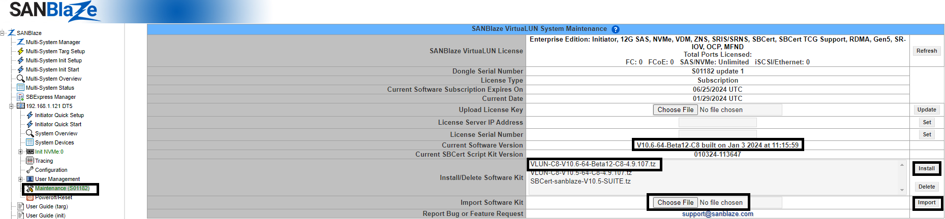
Within the Maintenance page, click the Choose File button located on the Import Software Kit row.
Select the .tz file provided to you by SANBlaze and then select Import. Importing the file may take a few minutes.
When the import has finished, highlight the new filename that is listed on the screen and select Install; a pop-up appears. Select OK. The installation begins; this may take a few minutes.
 Upon completion, a SANBlaze VirtuaLUN System Reset page appears. For example:
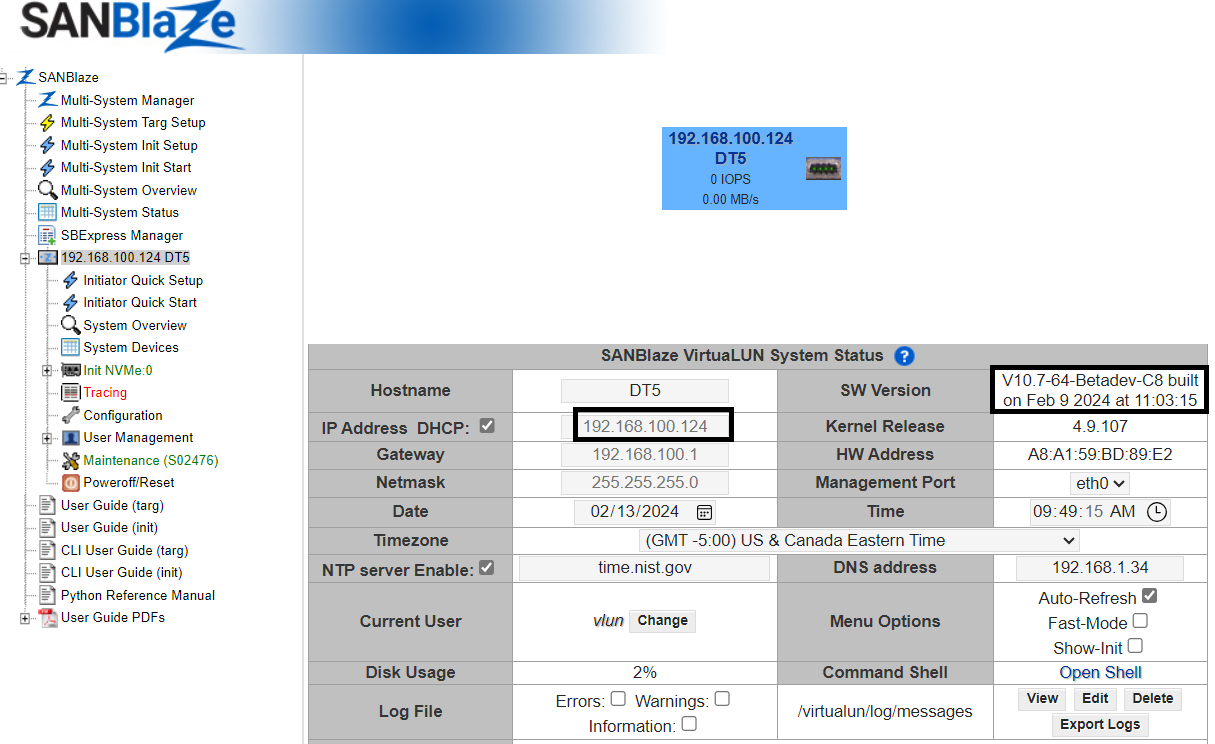
Click on the Reboot button. After the system has rebooted, the SBExpress page is displayed**,** showing the current software version that is associated with the IP address of the system. In the GUI example below, the software version is shown on the top of the right-hand column from the IP address (left-hand column) on the main page. In this example, the software version is V10.8-64-Betadev-C8; your version may vary but must be Version 11.0 or later.
Note
If you have Version 10.6 or lower on your system, the iRiser hardware will not work. Please update to one of the minimum software versions as previously described in this section for the version of iRiser you are using.
To check the software version from the CLI, use the following command:
grep Version= /proc/vlun/config
Verifying the SBR Images
Using your telnet or ssh session, verify that the required Serial Boot Records (SBRs) are present on the system.
The following SBR images are the [minimum] revisions required for iRiser support:
| RM5 V2/V3 (A0) | RM5 V2/V3 (B0) | RM5 V4 | DT5 | Description |
|---|---|---|---|---|
| 03b60505 | 03b71009 | 03b72105 | 03c01016 | Default |
| 03B60201 | 03b71200 | 03b72204 | 03c02004 | SRIS/SRNS |
To determine your system version, use the following pair of commands:
sb_i2c2 -d -3 -e \| grep Device

lspci \| egrep \"(DT\|RM)\[45\]\" -m 1
The last digit of the first command is the version number: i.e., 1, 2, 3, etc.
The last few characters of the second command will show if the rev is a0 or b0.
To get help for sb_flash
[root@RM5-100-164-IPMI-153 \~\]# sb_flash -help

INFO: Found Atlas-A0

USAGE: sb_flash \[show\] \[select N\] \[image \[index\|imageID\]\] \[-r\] \[-l\]

-r Force recovery mode (g4Xrecovery)

-l Force legacy mode (SwApps)
Examples:
Show the available images and currently selected flash:
sb_flash show
Select next boot flash image:
sb_flash select N (N = 0 - 3)
Flash an image by ImageID (see ImageID from show):
sb_flash show select N image ID
Flash an image by Index Number (see Index from show):
sb_flash show select N image I
Display SBR image configuration
To display the SBR image configuration for the system use: sb_flash show
[root@DT5 ~]# sb_flash show
INFO: Found 3c01016 flash image 0 at available_images 57
INFO: Found 3c01016 flash image 1 at available_images 57
INFO: Found 3c01016 flash image 2 at available_images 57
INFO: Found 3c01016 flash image 3 at available_images 57
INFO: System = DT5B0 sdb port=/dev/ttyACM0 Selected SBR Flash=0 Showing compatible images
Index ImageID Type Ver Mode UpLNK SSC/CFC Clock System Description
Active: 58 03c01016 10 16 Base 10 CFC CC DT5B0 DT5 Default
60 03c01202 12 02 Base 10 CFC CC DT5B0 DT5 Default
64 03c02004 20 04 Base 10 SSC SRIS DT5B0 DT5 SRIS
66 03c02100 21 00 Base 10 CFC CC DT5B0 DT5 DPR Off; Dual Port
67 03c02200 22 00 Base 10 CFC CC DT5B0 DT5 DPR Off; Single Port

INFO: Current Active Images:
Index ImageID Type Ver Mode UpLNK SSC/CFC Clock System Description

Active: 0 03c01016 10 16 Base 10 CFC CC DT5B0 DT5 Default
1 03c01016 10 16 Base 10 CFC CC DT5B0 DT5 Default
2 03c01016 10 16 Base 10 CFC CC DT5B0 DT5 Default
3 03c01016 10 16 Base 10 CFC CC DT5B0 DT5 Default
In the above example, the DT5 default SBR 03c01016 is in eeprom index 0 and is active. This is the SBR image that is needed for the DT5. If your SBR image is not the default, follow the steps below.
If you want to upgrade the default SBR from 03c01016 to 03c01202:
[root@DT5 ~]# sb_flash select 0 image 60
INFO: Selecting flashindex=0
INFO: Found 3c01016 flash image 0 at available_images 57
INFO: Found 3c01016 flash image 1 at available_images 57
INFO: Found 3c01016 flash image 2 at available_images 57
INFO: Found 3c01016 flash image 3 at available_images 57
INFO: System = DT5B0 sdb port=/dev/ttyACM0 Selected SBR Flash=0 Showing compatible images
INFO: Selecting Flash Index=0, Image Index=59 Write File filename=RDK_B0.RC.pre_15_Sblz_DT5_03C01202.signed.bin
INFO: readFlash successfully read 2156 bytes
INFO: Doing cmd=diff -q /tmp/firmware/0/write_test.sbr /tmp/firmware/0/\
write_test.sbr.unsigned

INFO: Successfully uploaded Flash at Index=0 from file /virtualun/firmware/atlas/
sbr_images/B0/DT5/RDK_B0.

RC.pre_15_Sblz_DT5_03C01202.signed.bin
INFO: Found 3c01202 flash image 0 at available_images 59
INFO: Found 3c01202 flash image 1 at available_images 59
INFO: Found 3c01202 flash image 2 at available_images 59
INFO: Found 3c01202 flash image 3 at available_images 59
INFO: Current Active Images:
Index ImageID Type Ver Mode UpLNK SSC/CFC Clock System Description

Active: 0 03c01202 12 02 Base 10 CFC CC DT5B0 DT5 Default
1 03c01202 12 02 Base 10 CFC CC DT5B0 DT5 Default
2 03c01202 12 02 Base 10 CFC CC DT5B0 DT5 Default
3 03c01202 12 02 Base 10 CFC CC DT5B0 DT5 Default
The word Next appears near the selected Default SBR.
After the Default SBR has been selected, power cycle the system using the following command:
[root@DT5 ~]# poweroff
Wait 30 seconds, then turn the unit back on by pressing the checkmark button on the front of the DT5.

Verify that the Default SBR is Active
After the SBExpress**-**DT5 is back up and running, use the sb_flash show command to verify that the active SBR image 03c01016 is the Default SBR. For example:
[root@DT5 ~]# sb_flash show
INFO: Found 3c01202 flash image 0 at available_images 59
INFO: Found 3c01202 flash image 1 at available_images 59
INFO: Found 3c01202 flash image 2 at available_images 59
INFO: Found 3c01202 flash image 3 at available_images 59
INFO: System = DT5B0 sdb port=/dev/ttyACM0 Selected SBR Flash=0 Showing compatible images
Index ImageID Type Ver Mode UpLNK SSC/CFC Clock System Description

Active: 58 03c01016 10 16 Base 10 CFC CC DT5B0 DT5 Default
60 03c01202 12 02 Base 10 CFC CC DT5B0 DT5 Default
64 03c02004 20 04 Base 10 SSC SRIS DT5B0 DT5 SRIS
66 03c02100 21 00 Base 10 CFC CC DT5B0 DT5 DPR Off; Dual Port
67 03c02200 22 00 Base 10 CFC CC DT5B0 DT5 DPR Off; Single Port

INFO: Current Active Images:
Index ImageID Type Ver Mode UpLNK SSC/CFC Clock System Description
Next: 0 03c01202 12 02 Base 10 CFC CC DT5B0 DT5 Default
1 03c01202 12 02 Base 10 CFC CC DT5B0 DT5 Default
2 03c01202 12 02 Base 10 CFC CC DT5B0 DT5 Default
3 03c01202 12 02 Base 10 CFC CC DT5B0 DT5 Default

WARN: System is booted using unknown SBR image, next boot will select SBR flash 0
Note
Using -3 in this command specifies that changes should be written to the motherboard.
You can issue any of the following commands to return the GPIOs back to their default settings:
 iriser -d -3 set sw7
 iriser -d -3c clear sw6
 iriser -d -3 set sw2
 iriser -d -3c clear sw1
Getting Started with the GUI
You can access iRiser commands via the Graphical User Interface through the SBExpress menu to change settings in the GPIO and Signals tabs.
From the SBExpress Manager menu, follow these steps:
Click on SBExpress Manager in the left-hand menu
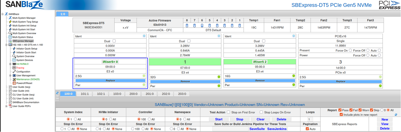 Locate the slot(s) that have an iRiser device populated and click on the grey identifier (e.g., “iRiser5+ 0” or “iRiser5 2”)
A pop-up window appears showing the GPIO signals for the iRiser device selected**:**
iRiser GPIO Tab
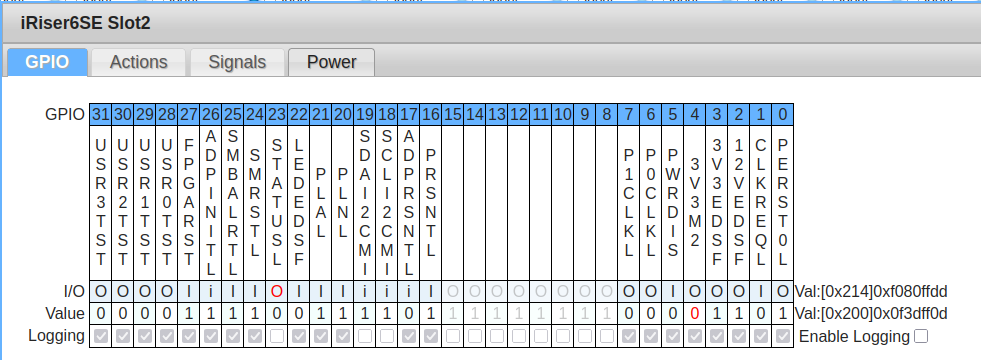
The GPIO tab is the first tab available in the iRiser GUI. This tab is designed to be a live graphical view of the current iRiser signals. It allows the user to interact with the signals, turning them on and off with the click of a button. Below you can see a screenshot of the page.
Starting from the top, you can see the table shows the GPIO number of each signal on the iRiser. Underneath, you can see which signal name corresponds to this GPIO number. As iRisers are updated in the future, these values will automatically reflect the signals of whichever iRiser is currently being looked at.
Moving down a little, you can see a row for I/O values. This row shows the signal’s direction:
‘I’ corresponds to ‘Input’ and ‘O’ for ‘Output’
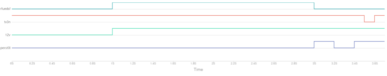
If a signal’s I/O value is marked with a lower case ‘i’ or ‘o’, this means the signal is locked to that direction and cannot be changed. Clicking on an element in this row will send the request to the iRiser to change that signal’s I/O direction to the opposite of what it is currently set to. Take the signal “Tx3N” below:
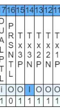
Hovering over a value in this row will also provide additional information about the signal.
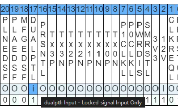
The next row of the table is the ‘value’ row. This is the current state of the signal. ‘1’ indicates the signal is on, ‘0’ indicates it is off. Like the ‘I/O’ row above, clicking any of the elements in this row will automatically set this value to the opposite of what is currently on screen and update the iRiser accordingly.
As mentioned previously, this page is a live view of the signals. When interacting with the drive outside of the iRiser (e.g. powering it on or off), these signals will automatically change in order to reflect the current state. This may take a few seconds to do so.
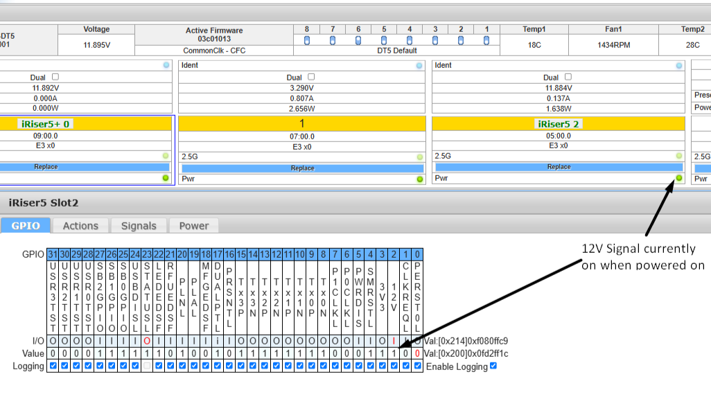 Here is an example showing the 12V signal while the device is powered on:
After clicking the power off button in the SANBlaze GUI, the 12V value is automatically updated to reflect the 12V power state and is switched to a ‘0’ value.
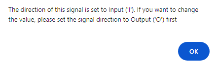
Note
You can’t change the value if the direction is an input; you would need to change it to an output first, then you can change the value.
If you try to change the value on an input, this message will pop up:
Note
Some iRisers do not have signal names for all GPIO’s. Columns in this table without signal names will be automatically disabled and cannot be toggled on or off from the GUI.
GPIO Logging
The iRiser GPIO GUI tab provides a visual representation of the current GPIO logging status. That tab also contains a bottom row for GPIO logging.
Each signal contains a checkbox. If a checkbox is checked, GPIO logging is turned on for this signal. If it is left unchecked, GPIO logging is turned off for this signal.
Some signals may have their checkboxes disabled; this indicates the signal’s GPIO logging cannot be turned on. You can view the status of a signal by moving the cursor over the checkbox.
At the right-hand side of the logging row, you can see one additional checkbox. This is to enable and disable the logging functionality in its entirety. If this checkbox is unchecked, the logging functionality will be turned off which in turn also disabled every checkbox on this row.
iRiser Actions Tab
The Actions tab is designed to enable a user to create “Actions” and “Sequences” from a graphical user interface.
The iRiser is programmed by means of loading Actions and Sequences of Actions to the device which are then executed changing the specified GPIO signals. Sequences are simply defined as groups of Actions that are linked together and either end in a “stop” (Sequence will run once and stop) or the index of another Action. If an Action points to the first Action in the Sequence, the Sequence will loop until stopped.
If the Sequence is a loop and the system reboots, after the system comes back up, the Sequence will continue running. The blue status LED on the front of the iRiser will be blinking. If the Sequence is not a loop, after it stops running, the blue status LED on the front of the iRiser will stop blinking.
There are 128 “slots”, each of which can hold an Action, and a Sequence can be one or more Actions; up to 128 Actions can be defined in a Sequence.
This page aims to make it simpler to create and modify Sequences with a clear visual representation of what the signal states looks like for each Action (both direction and value); which Actions are in the Sequence and a chart showing how the Sequence looks in its timeline.
There are 3 main segments to this Actions tab that we will cover in this documentation:
A table showing Signals and Actions
A chart showing Signal state vs. time
A section to edit, delete and add new Actions
Starting from the top
At the top of the page, you’ll notice a light blue bar, shown below.
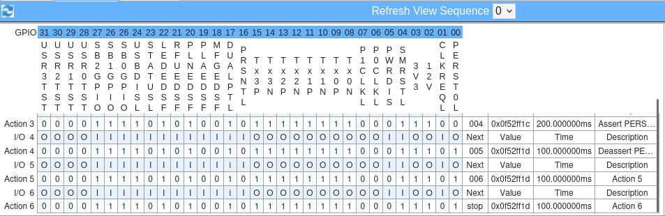
This bar holds 2 elements of the page: a ‘refresh’ button and a ‘Refresh View Sequence’ drop-down:

On the left-hand side, you’ll see a ‘refresh’ button. When clicked, this button will refresh all elements on this page. It also updates the drop-down in this top bar if you do not want to wait the 10 seconds it takes to refresh.
The refresh button itself is useful if you use scripts or commands to modify Sequences from the cli and want to quickly update what is on screen to represent the new state of the current selected Sequence.
In the center of that bar, you’ll see a ‘Refresh View Sequence’ drop-down menu. This drop-down includes all the currently active Sequences on the current iRiser. This drop-down is automatically updated every 10 seconds to add or remove Sequences, based on which Sequences are on the iRiser.
GPIO Signal Table
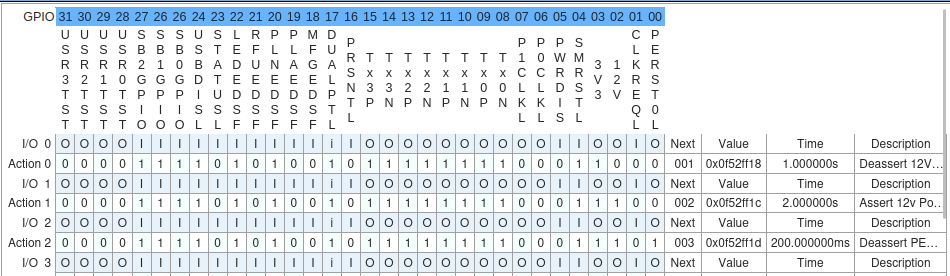 The Signal Table is an interactive table that shows all the Actions of the Sequence selected.
What you see above is a similar layout to the output from the cli command:
iriser -d <slot\ show sequence {sequenceNumber}
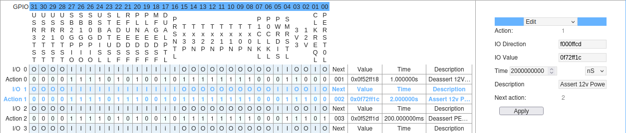
In blue at the top is each GPIO bit number for the signal it represents. Directly underneath is the full string name of that signal.
Clicking on either of these 2 elements will highlight the column. Clicking on the column again will remove the highlight. Only 1 column may be highlighted at a time. This is a useful way to visually distinguish the values for the signal highlighted.
User interaction with the GPIO Signal Table
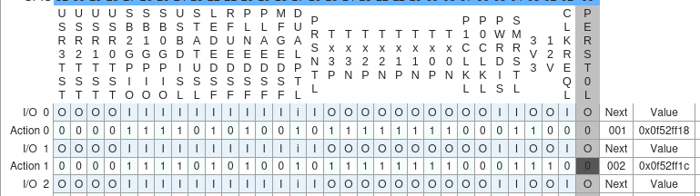
Below the GPIO signal name row are each of the Actions included within this currently selected Sequence. Each Action has 2 rows, the upper one that represents the direction of signals in the Action and the lower represents the state (value) of the signals in the Action.

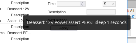
To the right most side of the table, you’ll see each Action also contains columns that represent which Action it points to next, what this Action value is as a hex value, the time the Action will run for, and any description / name associated with that Action. Actions that have too large a description contain a hover over text to fully show what the description is.
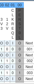
You can click on an element in the table to change it. For example, if you wanted to change the signal state of Perst in Action 1, you could find the column and row associated with this signal and Action and click it to change the value. See below:
Before the change, the signal was set to be off at Action 1 in the Sequence. represented by the value”0”. After the change the signal now has a value of “1” showing the signal will be turned on for this Action.
This value change is instantly applied upon click!
(Note – For the image above, the column highlight was on to help show what was changed)
Please use this table below to check what each value character in the chart represents.
| Character | Row | Meaning |
|---|---|---|
| 0 | Direction | The Direction of the signal is set as an output |
| I | Direction | The Direction of the signal is set as an input |
| i | Direction | The Direction of the signal is locked to input and can't be changed |
| o | Direction | The Direction of the signal is locked to output and can't be changed |
| 0 | Value (state) | The State of the signal is OFF for this Action |
| 1 | Value (state) | The State of the signal is ON for this Action |
Note
If you attempt to change a locked bit, the GUI will alert you with a reason why this value will not be changed.
You may have noticed; the Action row has now turned blue. This serves a purpose, but we’ll go over this in more detail when talking about the editing, adding and deleting Actions later.
 For larger Sequences, the number of Actions may exceed the boundaries of the table. However, the table is scrollable, and for convenience, the header rows are static so you can always see the signal name of each column.
Note
Some iRisers do not have signal names for all GPIO’s. Columns in this table without signal names will be automatically disabled and cannot be toggled on or off from the GUI.
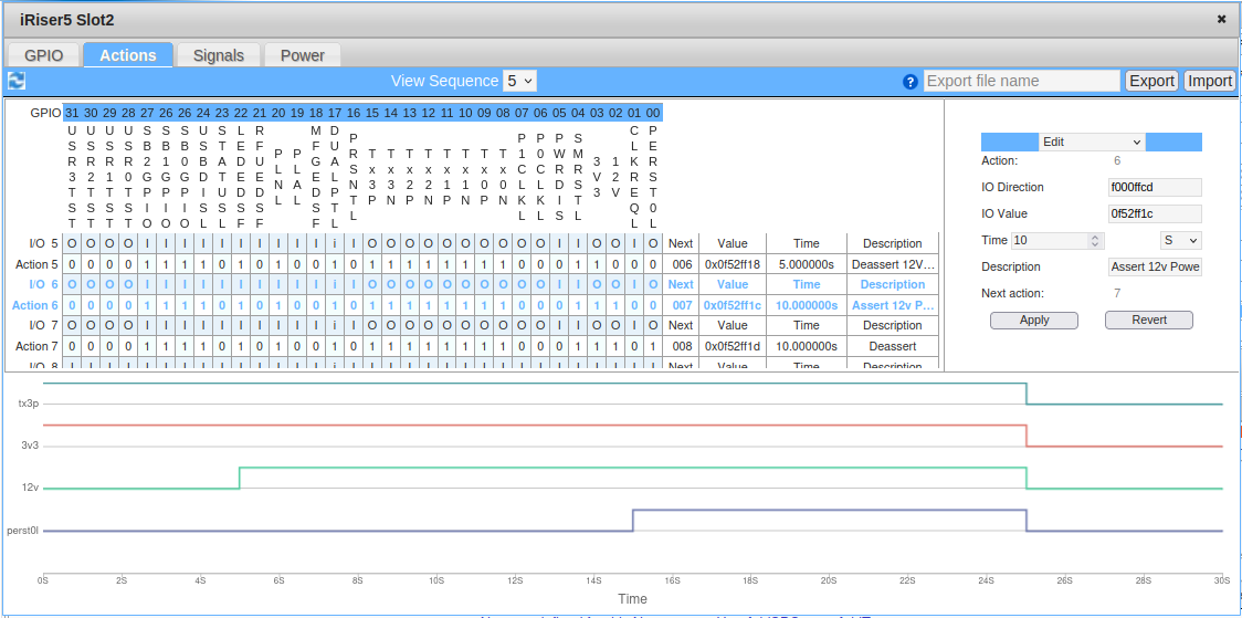
Signal chart
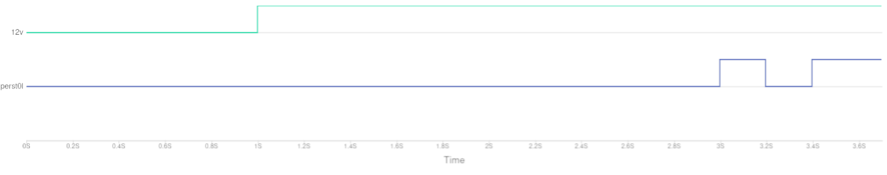 Below this table is a chart that represents the signal state vs. time. This chart is a step-line graph that shows only the signals that change in the Sequence and at what time in the Sequence they will change.
For example, in the image above, the “Perst0l” signal is off up until 3 seconds, where it is turned on for 0.2 seconds, turned off for another 0.2 seconds and turned on for the remainder of the Sequence.
 This chart will automatically update when changes are made to the Sequence via the signal table. If more signals are changed throughout the Sequence, more lines appear on the graph to represent these changes.
Editing, adding and removing Actions using the GUI
The last segment on this page is a table that allows you to quickly edit, delete and add new Actions to the currently selected Sequence. At the top of the section is a blue bar with a drop-down. In this drop-down there are 3 choices: Edit, Delete and Add new Action. Selecting an option from this drop-down will update the segment with new GUI elements based off of the item selected.
Editing Actions
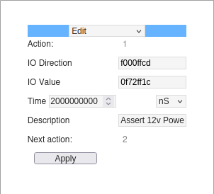
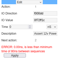
As editing an Action is the first item to appear, we will cover this first. Above, you’ll see a small table with the following items:
Action: (Locked) The number of the Action currently being edited
IO Direction: Hex value representation of the signal directions for this Action
IO Value: Hex value representation of the signal states for this Action
Time: The time this Action will run for. This has a box for a numeric value, followed by a drop-down to indicate if this value is in Nanoseconds, Microseconds, Milliseconds, or Seconds.
Description: A description for the Action
Next Action: The next Action this Action points to
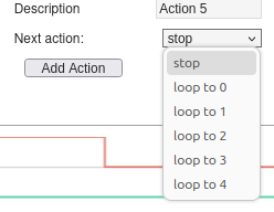
For the last Action in any Sequence, this next Action will instead be a drop-down that allows the user to select if they want the Sequence to stop after this Action is complete, or loop to another Action within the Sequence.
 To select an Action to be edited, the user needs to click on an item in the signal table to the left. As hinted earlier, this turns the Action rows blue which indicates that Action is currently being edited.
Clicking the Action will automatically populate the edit segment with the current values of that Action. If you change values by clicking within the signal table, these changes are automatically updated in the edit segment too.
Once the values have been populated into the edit segment, you can manually change them to fit your desired needs. For the changes in this edit segment to be applied, you must hit the “apply” button. If an error occurs during the application of the new values, an error will show, and no change will be made until this error is corrected and the user hit “Apply”.
Re-clicking the Action from the Action table will re-populate and override this edit segment with the current values of the Action clicked.
Deleting Actions
Selecting “Delete” from the drop-down menu in this segment will display new GUI elements to allow you to delete Actions.
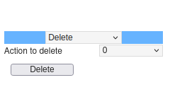
This “Delete” view only contains 2 items: A drop-down to select the Action you wish to delete and a Delete button to delete the current Action selected in the drop-down.
The Actions listed here are only for the Sequence currently selected on screen. Changing to another Sequence or adding new Actions to the current Sequence will automatically re-populate this drop-down with the current Actions in this Sequence.
Every time the user presses the delete button, it will prompt the user with a confirmation dialog to confirm whether they really want to delete the Action. Deleting an Action mid-Sequence will make the Action prior to the deleted Action point to the Action following the deleted Action (if applicable).
For example, you select Sequence 0. It has 5 Actions.
Action 0 –\ Action 1 –\ Action 2 –\ Action 3 –\ Action 4 –\ Stop
You choose to delete Action 2 from the Sequence. The Sequence now looks like this.
Action 0 –\ Action 1 –\ Action 3 –\ Action 4 –\ Stop
Deleting an Action at the start of the Sequence is slightly different in that the Sequence will now be renamed to the second Action in the Sequence or should there not be a second Action, the Sequence will be deleted.
For example, if you select Sequence 0 from before, it has 5 Actions. You delete Action 0. The Sequence is now called Sequence 1 and contains the rest of the Actions.
Action 1 –\ Action 2 –\ Action 3 –\ Action 4 –\ Stop
Adding Actions
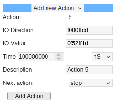
The last segment / view to talk about is the “Add new Action”. This segment is designed to make it as simple as possible to add new Actions to the currently selected Sequence.
It should be noted that users can only add new Actions to the end of Sequences, not mid-way through.
This layout is very similar to the Edit Action layout, however there are a few distinct differences.
Firstly, the Action number of the new Action is chosen for you. While you can choose an Action number in the CLI, the GUI automatically assigns the next suggested ‘best’ Action number for you. This is chosen to be the next numerical incremented value to whatever the last Action in the Sequence is.
For example, if you have a Sequence that consists of Actions numbered 1, 2 and 3 the newly suggested Action number is 4. If 4 is unavailable it goes to 5 and so on.
If you have a Sequence that consists of Actions 20, 30 and 40, the newly suggested will be 41.
If you have a Sequence that consists of Actions 20, 10, and 5, the newly suggested Actions number will be 6.
Second, the ‘Next Action’ value is a drop-down to allow you to choose if the Sequence should stop after this Action or loop to another Action. Remember, when this Action is added, it will be the new last Action in the Sequence.
Third, when selecting the ‘add new Action’ from the drop-down, it will automatically populate the fields using the current last Action’s fields. For example, if the last Action currently has a time of 100mS, the add Action will automatically populate with 100mS. If the last Action has an IO direction hex value of “f000ffcd”, the add Action will automatically populate with an IO direction hex value of “f000ffcd”.
Lastly, instead of an ‘Apply’ button you now have an ‘Add Action’ button. This button will create the new Action, with the values specified, and add it to the end of the current selected Sequence. Once the Action is added, the other elements on screen will update to show this newly added Action. Additionally, this “Add new Action” segment will re-populate with the suggested next Action number after the one that was just added.
Import and Export Configuration Files
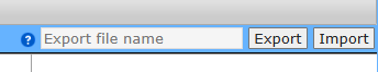
In the top right-hand corner of the Actions tab are two buttons to import and export config files. A config file is a file that contains the current state of the iRiser Sequences and Actions when the config file was produced.
This allows you to create a Sequence layout on one iRiser, save it, and then easily upload it to many other iRisers. This can be useful for setting up new iRisers in a system or sending the configuration of your iRiser to a colleague in order to run a Sequence that might be causing your drive issues.
The text box allows you to write a name for the config file to be saved as. Note: the filename is limited to 64 characters. If no name is specified, the file will be named “iRiserConfig-YY-MM-DD-HH-MM-SS.cfg” according to the current date and time the config file was created. Please note, while the name of the config file can be altered, we recommend you do not edit the contents as malformed config files will not be loaded onto the iRiser.
Note
The following special characters cannot be used in the exported file name. Doing so will automatically replace these characters with the underscore character. Special characters not allowed: | \ / : * ? “ \ < If used, they will be automatically replaced with the _ (underscore) character.
Clicking the export button will then download the newly created config file to your system, as seen below.

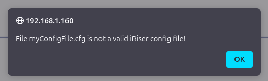
The import button is used to import config files onto the iRiser. Clicking this button opens a file explorer to allow you to select the config file. Once selected, it will automatically upload the file and refresh the Actions tab accordingly to reflect the changes. If the config file is bad, the page will alert you that the config file has not been accepted.
iRiser Signals Tab
 The Signals tab is designed to visualize Sequences on the iRiser as a chart of “signal state” vs. time. To do this, the page automatically requests information from the iRiser in the background that is used to update current Sequences found, whether a Sequence is running, and when a Sequence is updated.
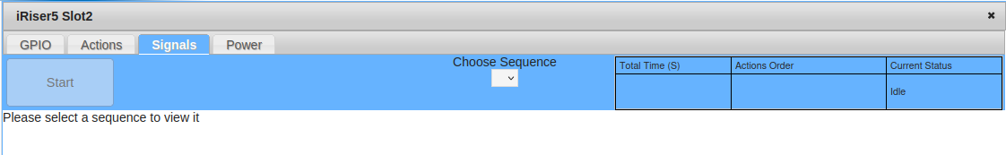
When first navigating to the tab, you’ll be presented with one of the 2 states below.
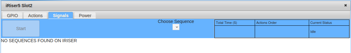 This first state informs the user that there are no Sequences currently found on the iRiser. To add new Sequences, the user must use the iRiser program on the CLI (see next section):
 Once a new Sequence is added, this page will automatically update within a few seconds and show the new state as seen in the image below:
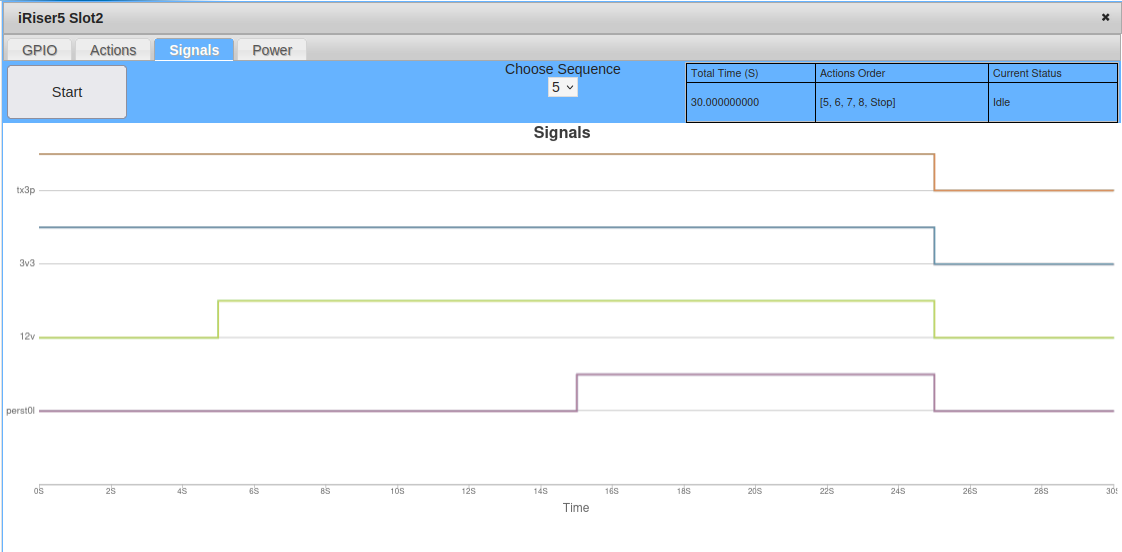
In the second state above, the page informs us there is at least 1 Sequence on the iRiser and it can be selected to view it.
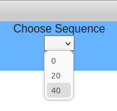
Selecting a Sequence
To select a Sequence to view, click on the “Choose Sequence” drop-down. Here you’ll find all the current Sequences discovered on the iRiser. If the user has recently added one or more additional Sequences, these may take up to 30 seconds to be added to the drop-down list.
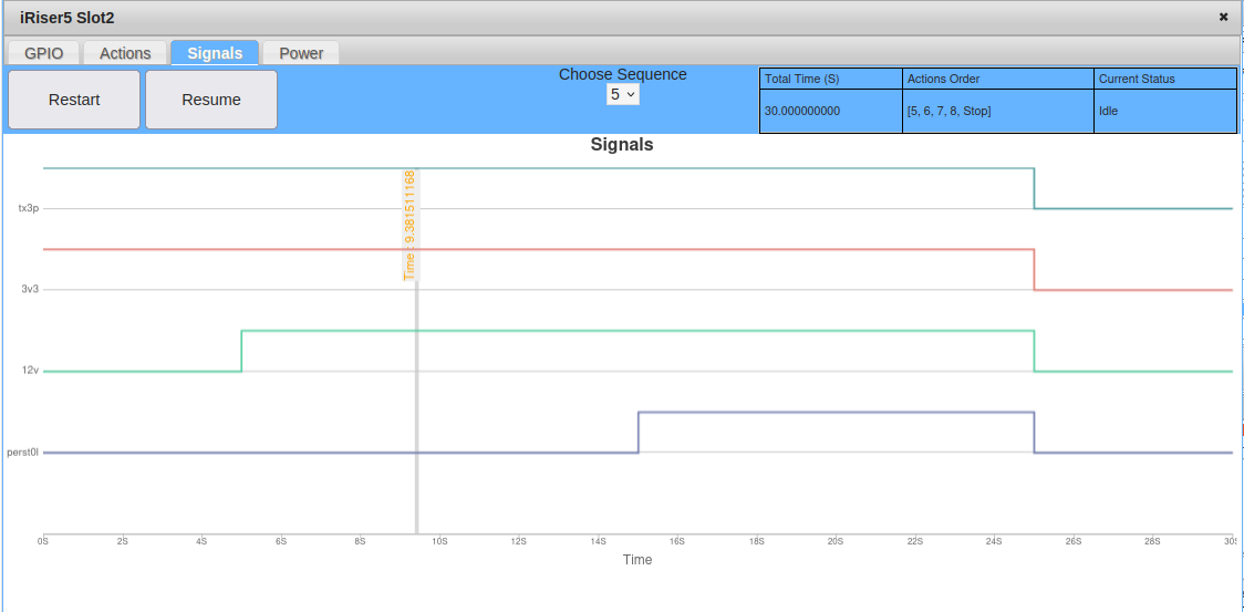
Upon selecting a Sequence from the drop-down, the page will automatically update to show a new chart with “signals state” vs time, alongside updating the table in the top right-hand corner to show some additional information about the Sequence.
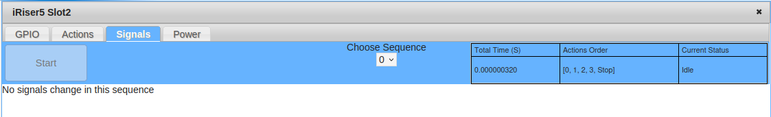 As the table headers read, the first column shows the total time of the selected Sequence in seconds, the second column displays a list of all the Actions within the Sequence and the third column shows the current state of the iRiser itself.
As you can see above, this selected Sequence is a total of 0.000000320 seconds long (3.2uS) long and contains Actions 0, 1, 2 and 3. The Actions order will also contain either a “Stop” Action, indicating this Sequence stops after this Action is complete, or a “Loop” Action that indicates this Sequence loops after the last Action.
This Sequence contains a set of Actions that do not change any signal states; therefore, the page is now displaying a “No signals change in this sequence” instead of a graph.
Explaining the graph
As mentioned previously, the signal tab step-line graph shows signal state against time. This graph only shows the signals that change in the current Sequence to not over-populate the graph with signals. All signals that do not appear in this graph do not change state throughout the selected Sequence.
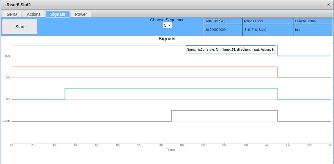 When hovering over the graph, a mouse-over label is visible at the Action and signals closest to the mouse cursor. This label shows the intended state of that signal at that Action, the time that the Action occurs within the Sequence, and the Action number.
Starting a Sequence
The last item on this tab is the “start” button. This is self-explanatory in that it is used to start the current selected Sequence. If the Sequence is started, this button changes to a “Stop” button. Pressing the “stop” button will stop the current Sequence at that point in the Sequence.
If a Sequence is stopped mid-Sequence, the “stop” button will now show a “restart” and a new “resume” button is shown alongside this. The restart button will now restart the Sequence from the first Action in the Sequence. The resume button will continue the Sequence from where it was last stopped.
A user can also start and stop a Sequence from the CLI. If a Sequence is started from the CLI, the signals tab will automatically retrieve this information and update the UI on screen to reflect this. If the user starts a Sequence different to that which is currently being shown on screen, the GUI will automatically select the running Sequence and show it on screen instead. While a Sequence is running, no other Sequence can be selected as the drop-down will be disabled until the Sequence is stopped.
Additionally, when the user starts a Sequence, the graph will display a red/grey (browser dependent) colored, horizontally scrolling strip-line. This will scroll in close to real time to give a +/- 100mS view of what / where in the Sequence is currently being executed.
 This may drift slightly more of sync if left to run on long Sequences (10 minutes or more) but will re-sync when the Sequence is stopped. When the user stops the Sequence, it will jump to the exact place in the Sequence that it was stopped.
iRiser Power tab
UPDATE - 11.0-Build5 - Live power recordings are now live, read more below.
This last iRiser GUI tab allows recording of power traces on the iRiser power rails, allowing the user to view the recording in real time or at a later date.
The recordings are saved to the directory specified when the recording is started. If the same name is used for multiple recordings, the GUI first prompts the user to confirm you wish to overwrite the older recording. If the user confirms this, the older recording will be overwritten in place of the new recording.
The first screen of the Power tab is shown below.
Please note that the display will differ slightly if iRiser5 is selected vs. iRiser5+ / iRiser6 / iRiser6SE.
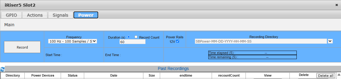 [iRiser5 view:]
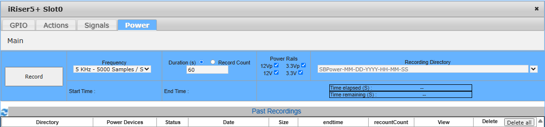 [iRiser5+ view (iRiser6 and iRiser6SE view will be very similar):]
This guide will start from the top and work down the page to explain each section.
At the top of the page, you will see a tab labeled ‘Main’. This is for the main power page which you can see in the above image. Tabs are used for navigating between recordings and back to this main page.
The Main tab is the only tab you cannot close on this page. Every other tab created while navigating through recordings will contain a red ‘X’ symbol. Clicking this will close the tab.
Creating Recordings
The main tab of this power display serves two functions.
The first is for creating new power recordings, the second is a table in which to see a summary table view of previous recordings.
When a recording is first started, the view will change to a live recording as of 11.0-Build5 release. This viewing live recordings functionality is described later in the documentation. However, before the recording is started the user has the option to change some recording variables, changing what is recorded and how long it’s recorded for.
Recording Variables
Directly under the recording tabs is a blue table containing elements that are used to make and view an ongoing recording. Along the top is a Frequency drop down (# of samples to be recording per second), a Duration (recording time limit) and Record Count limit, checkboxes used to select Power rails to record with and a Recording Directory text box with history drop down.
To the left-hand side is a record button that uses the values inside these table elements to start a power recording.
Lastly, at the bottom row of the table are Start Time, End Time and time elapsed / remaining table elements. These are used to provide the user data about any ongoing recordings and when they will finish.
Note
Please note that the display will differ slightly if iRiser5 is selected vs. iRiser5+ / iRiser6 / iRiser6SE.
 [iRiser5 view:]
 [iRiser5+ view (iRiser6 and iRiser6SE view will be very similar):]
The Frequency drop-down is listed in both Hz and the equivalent samples per second value. This offers a set selection of options ranging from 1Hz to the max frequency that the currently selected iRiser is capable of. See below for max values:
iRiser5
12V : 1MHz - ~1,000,000 samples / second
iRiser5+ / iRiser6 / iRiser6SE
3.3V / 12V : 500Khz - 500,000 samples / second
3.3Vp / 12Vp : 2900Hz - 2900 samples / second
1.8Vpa / 3.3Vpa : 2900Hz - 2900 samples / second
[Where:]
V (with no ‘p’ or ‘a’): power rail measured at 12-bit precision
Example: 3.3V is 3.3V measured at 12-bit precision
Vp : p = precise power rail; measured at 20-bit precision
Example: 3.3Vp is 3.3V measured at 20-bit precision
Vpa : p = precise power rail; measured at 20-bit precision and a = adapter
Example: 1.8Vpa, is 1.8V measured at 20-bit precision on the 660 M.2 adapter
Though the GUI only offers a set selection of options within those frequency ranges, the iRiser is capable of running at significantly slower frequencies than 1Hz. Additionally, a user can run at frequencies differing to those shown on the GUI (e.g. 200Hz, 150Hz, 20Hz are all acceptable values on the CLI but are not listed in the GUI due to space constrictions).
The Duration (s) and Record Count radio buttons are used for selecting the recording limit. Only one of these radio buttons can be selected at any time, and which one you pick determines when the recording will stop. The value specified in the text box below these radio buttons will be used as the corresponding value to whichever radio button option was picked. For example, if the “duration” radio button is checked, then the value specified in the text area will be time in seconds.
The Duration (s) radio button also allows you to input a total time for the recording in seconds. Once the recording hits this time limit, it will automatically stop recording. While the GUI only allows you to specify seconds, recording from the cli can be specified in microseconds (us) for recordings that need to be more precise.
The Record Count specifies the total number of records you wish to record before stopping. An example of this might be a recording that records at 100 samples per second (100Hz) and for 1250 record count. For this, once the ongoing trace has taken 1250 samples the recording will automatically stop. You can calculate the time taken for this by dividing record count by frequency (1250 / 100 = 12.5 seconds).
The Power Rails selection area is comprised of checkboxes representing the equivalent power rail on the iRiser. The available power rails represented here will change based on what is available on the currently selected iRiser.
To see what power rails are available on the current selected iRiser from the CLI, enter the command:
iriser -d <slot\ show power available
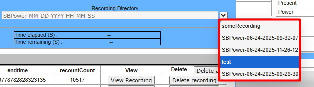
The Recording directory text area is the name of the recording. If this is left blank, a recording directory will be automatically added for you in the format “SBPower-MM-DD-YYYY-HH-MM-SS”. This recording directory will contain all of the power / voltage / current data for the recording.
To the right-hand side of the recording directory text box is a drop-down menu. This contains a list of all the names of previous recordings on the system. Selecting one of these items from the drop-down will replace the text inside the ‘recording directory’ text box with the drop-down element selected.
The *<Record* button is used to start the recording. It will take whatever values are currently set in the other 4 GUI elements and use them to start the recording.
Once the recording is started, the page will change to show the recording view showing the ongoing live recording. Additionally, in the background on this main tab, this button will change to show a ‘stop’ value instead.
When a recording is in progress, the iRiser recording status section of the page will also be updated in background, at a rate of once per second to show start, end and record count / time elapsed for the ongoing recording.
After the recording has reached its full allotted time (set in the duration / record count text area) or the recording has stopped for another reason*,* this button will change back to ‘record’.
iRiser recording status
 In the lower row of the table is the recording status for any ongoing recording. This section gets updated when a recording is started from the GUI or CLI to show the user the state of the current recording. The “start time” is the start time of the power recording, the “end time” is when the recording finished.
 For recordings started using the ‘duration’ option, the GUI will display a “time elapsed” and “time remaining” table that helps the user keep track of how long the recording has left. These values are updated every second. Additionally, for the recordings using “duration”, the recording’s End Time will be calculated immediately and shown on screen in the “end time” element.
 For the recordings started using the ‘record count’ option, the GUI will instead show a current record count for all power rails. These values are also updated automatically every second. The power rails shown are the ones currently being used in the recording. Once every power rail used in the recording has recorded the ‘target record count’ number of records, the recording will finish. As the end time for these types of recordings is unknown, the “end time” element will display as ‘Unknown’ until the recording has finished, where it will be automatically updated to show the real end time.
Past recordings table
This recording table is used to list all the past recordings saved to disk for this iRiser. The table is automatically updated when a recording is finished. You will know when a recording was added to the table as it will fade from blue to white. This is also automatically updated when the iRiser dialog is closed and re-opened. Inside the table are six columns.
Directory → This column contains the name of the directory the recording was saved to
Power devices → This column lists the voltage rails used for this recording
Status → Tells the current status of the recording
Date → When the recording was started.
Size → Size of the recording in bytes.
View → Populated with a button that, when clicked, loads the recording it is associated with.
Delete → Populated with a button that, when clicked, deleted the corresponding recording.
 When a recording is added, the table is populated with the recording’s variables as seen below.
Refresh icon
At the top left-hand side of this table is a refresh icon. Pressing it will refresh the table to check for new and updated recordings. This is useful if the user is recording using a test, or via the CLI and wants to re-update the GUI in order to view the recording. It will also delete recordings from this table and the tabs at the top of the page if the corresponding recording no longer exists.
A note on showing ongoing recordings
This page will check for ongoing recordings when any of the Actions below are performed:
The user closed and opened the page
The user hits the record button:
If there is already an ongoing recording when the user hits this button, an alert will appear on screen letting the user know a recording is already in progress.
Pressing ‘record’ will [not] stop the current recording, or start a new recording if one is ongoing.
The user hits the ‘refresh’ icon at the top of the past recordings table
Viewing recordings
The second view of this power tab is the recording view. This view is for displaying live recordings and past recordings in a navigable chart, while displaying additional useful information such as statistics about the data being displayed.
 This page will automatically be brought into view when the user starts a new recording. Alternatively, the user can click ‘View Recording’ in a row of the past recordings table to view an older recording.
At the top of the page, there will now be a newly opened tab with the name of this recording as the text in the tab. If the recording is live, the tab will also be prefixed with the string “(ACTIVE)” to show this tab is for the live recording, along with a blue text. In order to navigate back to the main page, hit the ‘main’ tab at the top of the page.

For live recordings, once the recording is finished, the page will automatically remove the prefix “(ACTIVE)” and change the text from blue back to black.
Live recordings
Live recordings are started immediately after the user hits ‘Record’ on the main tab, or if the user refreshes the page or opens the iRiser dialog whilst an ongoing recording is ongoing.
This live recording will pull down the last x amount of data at approximately 1 second intervals, and display this data on screen in the main chart. This will also update everything in the current selection window and recorded statistics view to this new data (more on this later).
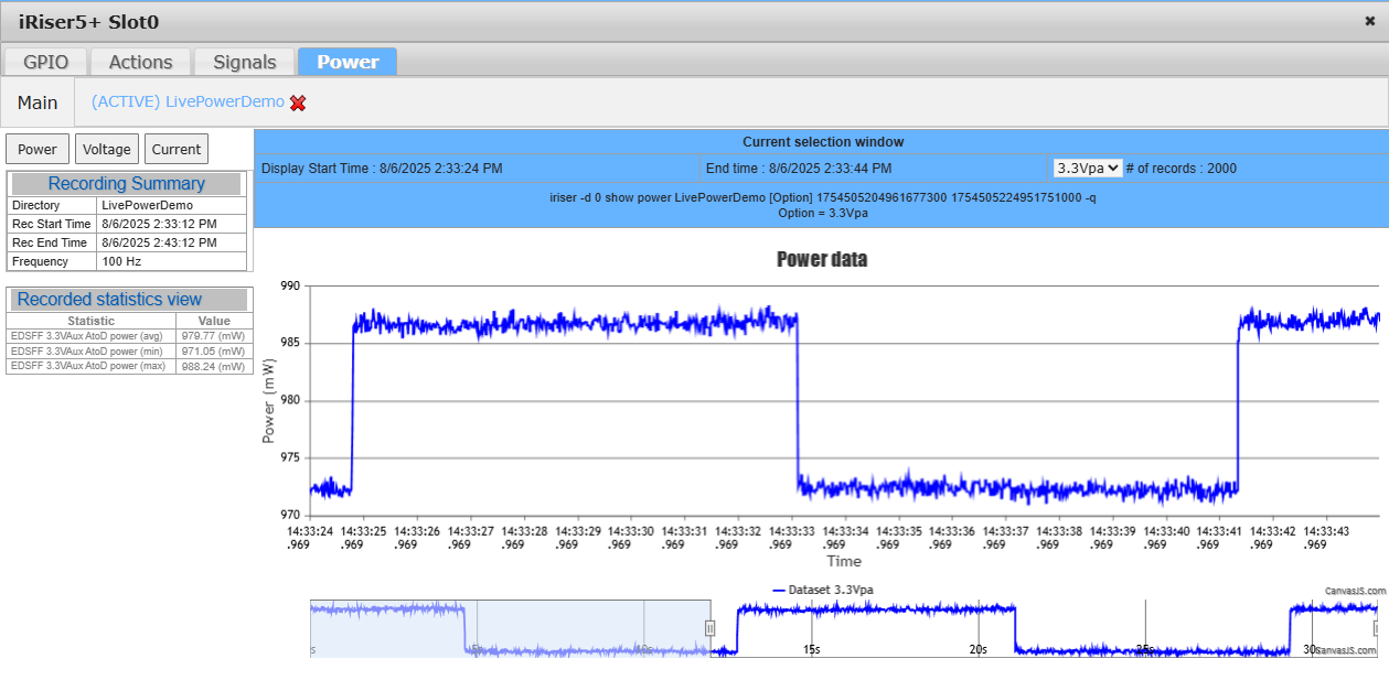
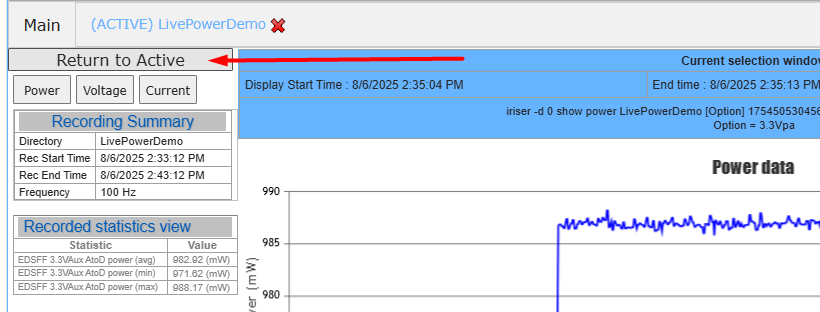
If a user chooses to zoom in on a section of the live recording, a new button will appear in the top left hand corner called “Return to Active”. This will reset what’s on screen to continue viewing live data, instead of the section that was just zoomed in on.
Once the live recording is complete, the page will update to show the recording as if it was a regular recording. This includes updating the data on screen to show data from the start of the recording as opposed to the last x amount of data from the live recording. This effect will not take place if the user was zoomed into a section on the chart before the live recording finished.
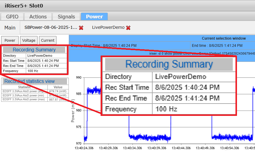
Recording summary
At the top left corner of the page is the Recording Summary table. In here is the recording’s directory name, the date and time the recording was taken and the sampling frequency this recording was taken at. This is automatically populated when a recording is viewed on screen:
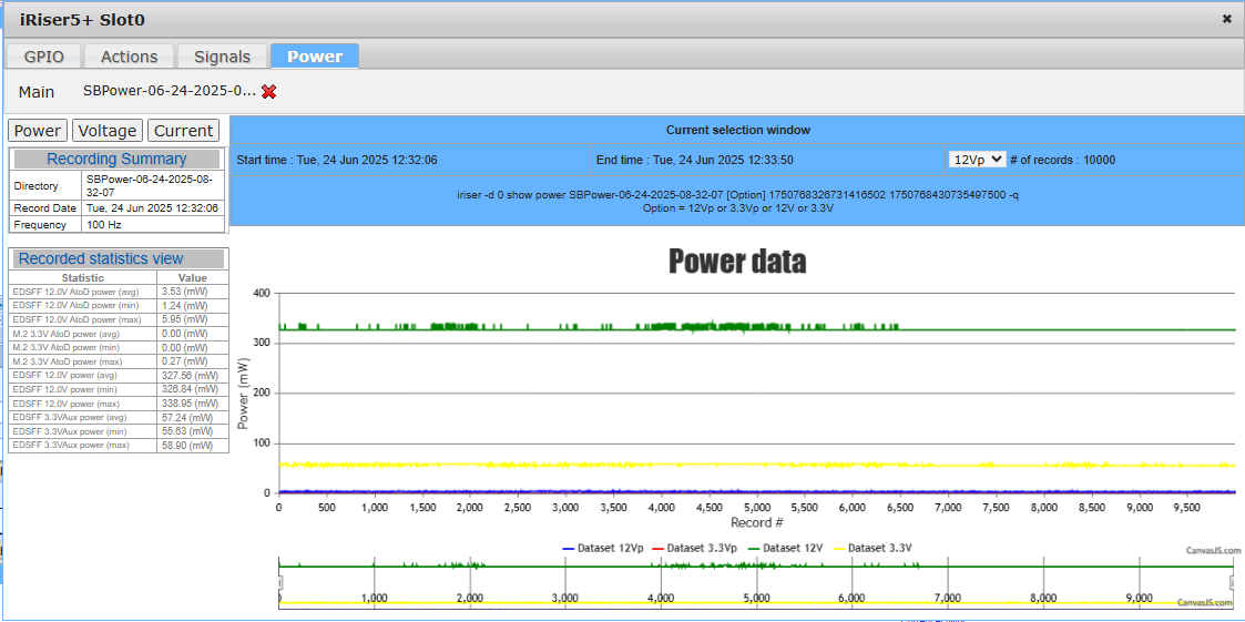
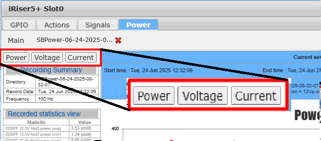
Current Selection window
This Current Selection window differs slightly from the recording summary window as it gives information on what data is currently displayed on screen. It will dynamically change with the data shown in the chart. This provides some useful information including the start and end time of the current selection window, the number of samples contained within this window and in the last row an iRiser command that you can copy and paste onto the cli to get this CSV data. The command requires you to replace the “[Option]” with one of the options displayed below.
For example, in this recording, the only options available are 12Vp, 3.3Vp, 12V and 3.3V. So, the command for getting the 12V data for this section would look like:
iriser -d 0 show power SBPower-06-24-2025-08-32-07 [12V]{.mark} 1750768326731416502 1750768430735497500 -q
Or for 3.3V, the command would be:
iriser -d 0 show power SBPower-06-24-2025-08-32-07 [3.3V]{.mark} 1750768326731416502 1750768430735497500 -q
The drop down next to ‘# of records’ provides an option to view the number of records for every power rail used in the recording. This is useful if you’re recording on an iRiser using ‘duration’ as the power rails being recorded may differ in the number of samples they record per second. Selecting an item from the drop down will automatically populate the value on screen.

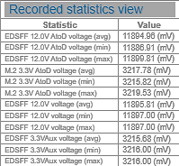
Recorded Statistics View
At the left-hand side of the page, there is a table labeled “Recorded statistics view”. This is a dynamically updating view containing statistics about the current selection window’s data.
This will automatically update every time a new selection is made in the chart. This happens when a user zooms in / navigates around the data using the timeline, or when the data is updated on screen during live recordings. It will display information about all the power rails used within the recording and give an average, max and min value for the measurement type currently in view.
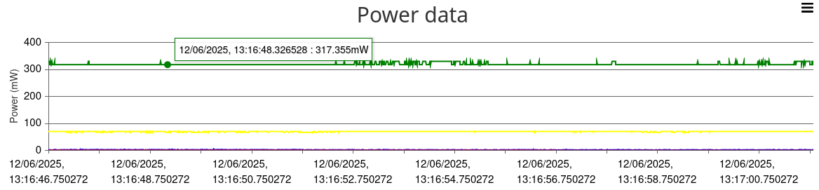
Recorded data charts
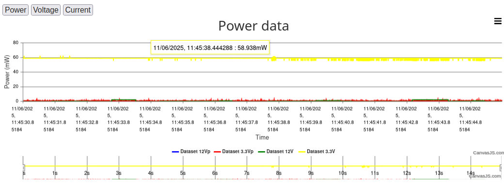 The last and main part of this view is the data chart. This chart displays the CSV data collected during the recording in a navigable chart.
There are 2 sections to each chart, a timeline view across the bottom 1/4 and the main view spanning the rest of the space. This type of chart is used as some recordings may be many millions of samples in size and the webpage would be unable to load all of these samples into memory.
Depending on the type of recording used, the chart will be created using either ‘record numbers’ or ‘time’ as the x-axis:
If a recording was complete using the ‘record count’ option, the chart will be displayed using record number as the x-axis.
If the recording is completed using a ‘duration’ option, the chart will display with a time-based x-axis.
At the top left corner of the page are 3 buttons: Power, Voltage and Current. Clicking any of these will change to the corresponding power/current/voltage chart.
Timeline view and navigation
The timeline view is a down-sampled overview of the entire recording. It is used to navigate through the full recording. To change what section you are currently viewing on screen, you can either left-click a section of the timeline view that is shaded over, or move one of the vertical sliders (seen on the screenshot below at 15 and 30 seconds respectively). The area between the sliders is what will be shown on the main chart.
 If the area selected on the timeline exceeds a maximum limit of onscreen samples set by SANBlaze, the sliders may move automatically to re-align with what is actually displayed on screen. As mentioned previously, this is a restriction put in place as the GUI can only safely handle a certain number of samples on screen due to memory restrictions.
 Main chart
As mentioned above, the main chart is a full, non-down sampled view of the data within the selected window on the timeline. The axes ranges are automatically set via the CanvasJS rendering functionality to best suit what is on screen.
To zoom in to this chart, the user can either left-click and drag on one of the sliders on the timeline, or alternatively left-click and drag on the main chart to zoom in on that current section. Zooming out however, can only be done using the sliders on the timeline.
Mousing over the chart will display information about the data sample closest to the cursor. On the screenshot above, the charts using ‘time’ as an x-axis will display the time of the current moused over sample and its value at that moment. For charts using ‘record number’ as the x-axis, the mouse over tooltip will show record number and value.
Getting Started with the CLI
This section describes:
Identifying the slots containing an iRiser.
Populating slots with iRiser hardware
Command Structure used.
Displaying the iRiser current state of signals.
Manually setting or clearing a control signal.
How to Save, Store, and Share .cfg and .sh Files.
Find iRisers on PCIe.
Using Read and Write commands.
Setting the GPIOs to Initial Default State.
Writing the GPIO Registers as 32-bit Values.
Setting I/O and GPIO Values from a File.
Verify the Device Under Test is Linked Correctly.
Identifying Slots Containing an iRiser
Because iRisers can coexist with standard SANBlaze risers, use the following command to identify which slots contain an iRiser:
sb_i2c2 -d a -i

INFO: System 01\[MB\] SBExpress SN=64fc8ad9 Rev=R01 i2c=/dev/i2c-0 SDB=/dev/ttyACM0 VLUN=0
INFO: Slot Main MI Priv p t l PCIe Prsnt Latch Width Speed Power BlueLED RiserID
INFO: \-\-\-- \-\-\-- \-\-\-- \-\-\-- \-\-- \-\-- \-\-- \-\-\-\-\-\-- \-\-\-\-- \-\-\-\-- \-\-\-\-- \-\-\-\-- \-\-\-\-- \-\-\-\-\-\-- \-\-\-\-\-\-\-\--
INFO: 0 0 1 none 0 100 1 09:00.0 1 0 4 5 1 1 600952000
INFO: 1 0 1 none 0 101 1 07:00.0 1 0 4 4 1 0 600952000
INFO: 2 0 1 3 0 102 1 05:00.0 1 0 4 4 1 0 600957003
In the above example, the iRisers are located in slots 0 and 1, and are identified by the RiserID of 600952xxx.
Populating Slots with iRiser Hardware
For SBExpress-RM5:
Only iRiser5 and iRiser5+ devices can be installed in RM5
A maximum of [four] iRiser devices are supported and can be installed in slots 6, 7, 8 or 9
For SBExpress-DT5:
Only iRiser5 and iRiser5+ devices can be installed DT5
A maximum of [three] iRiser devices are supported and can be installed in slots 0, 1, or 2
For SBExpress-RM5+ or RM6:
Only iRiser6 and iRiser6SE devices can be installed in RM5+ or RM6
Up to 16 iRiser devices are supported
Command Structure
iRiser commands use the following structure:
iriser <-d\ <slot# of the iRiser\ <action\ [feature]
Where: < \ = required and [ ] = optional
Help is available and is context sensitive to the -d # of the device:
iriser -d <slot\ help : for iRiser device installed in chassis slot 0
Additionally, help can be displayed for specific Actions and/or features:
*iriser -d <slot\ help <action* :shows help for the Action specified
Available Actions: [read]|[write]|[show]|[dump]|{set]|[clear]|[start]|[stop]|[reset]|
[init]|[status]|[config]|[edit]|[mirror]|[unmirror}|[input]|[output]|
[direction]
Note that the parameter [dump] prints the FPGA registers and is mostly for internal use.
*iriser -d help <slot\ <feature* : shows help for the feature specified
Available features : [action|sequence|logging|power]
3. *iriser -d <slot\ help <action\ <feature* : shows help for the Action on a
specified feature that is supported
by that Action
Specific commands and examples are shown below.
Checking the Current State of Signals
The following command shows the names and state of the signals under iRiser control:
iriser -d \<slot\ show gpio

(Default GPIO settings shown below)

Direction: I/O (UC) user writable signal, i/o (LC) signal locked

GPIO│31 24│23 16│15 8│7 0│

├─┬─┬─┬─┬─┬─┬─┬─┼─┬─┬─┬─┬─┬─┬─┬─┼─┬─┬─┬─┬─┬─┬─┬─┼─┬─┬─┬─┬─┬─┬─┬─┤

│U│U│U│U│S│S│S│S│S│L│R│P│P│M│D│P│T│T│T│T│T│T│T│T│P│P│P│S│3│1│C│P│

│S│S│S│S│B│B│B│B│T│E│F│L│L│F│U│R│x│x│x│x│x│x│x│x│1│0│W│M│V│2│L│E│

│R│R│R│R│G│G│G│G│A│D│U│N│A│G│A│S│3│3│2│2│1│1│0│0│C│C│R│R│3│V│K│R│

│3│2│1│0│P│P│P│P│T│E│E│E│E│E│L│N│P│N│P│N│P│N│P│N│L│L│D│S│ │ │R│S│

│T│T│T│T│I│I│I│I│U│D│D│D│D│D│P│T│ │ │ │ │ │ │ │ │K│K│I│T│ │ │E│T│

│S│S│S│S│O│O│O│O│S│S│S│S│S│S│T│L│ │ │ │ │ │ │ │ │L│L│S│L│ │ │Q│0│

│T│T│T│T│3│2│1│0│L│F│F│F│F│F│L│ │ │ │ │ │ │ │ │ │ │ │ │ │ │ │L│L│

├─┼─┼─┼─┼─┼─┼─┼─┼─┼─┼─┼─┼─┼─┼─┼─┼─┼─┼─┼─┼─┼─┼─┼─┼─┼─┼─┼─┼─┼─┼─┼─┤

│O│O│O│O│I│I│I│I│I│I│I│I│I│I│i│I│O│O│O│O│O│O│O│O│O│O│I│I│O│O│I│O│Dir:\[0x214\]0xf000ffcd

├─┼─┼─┼─┼─┼─┼─┼─┼─┼─┼─┼─┼─┼─┼─┼─┼─┼─┼─┼─┼─┼─┼─┼─┼─┼─┼─┼─┼─┼─┼─┼─┤

│0│0│0│0│1│1│1│1│1│1│0│1│0│0│1│0│1│1│1│1│1│1│1│1│0│0│0│1│1│1│0│1│Val:\[0x200\]0x0fd2ff1d

└─┴─┴─┴─┴─┴─┴─┴─┴─┴─┴─┴─┴─┴─┴─┴─┴─┴─┴─┴─┴─┴─┴─┴─┴─┴─┴─┴─┴─┴─┴─┴─┘
Alternative format for the same output:
iriser -d \<slot\ show gpio2 (or gpio1)

Bit Name Val Description

\-\-- \-\-\-- \-\-- \-\-\-\-\-\-\-\-\-\--

00\[I\] PERST0L 1 Setting low asserts perst

01\[I\] CLKREQL 0 Setting low asserts clkreq

02\[O\] 12V 1 Setting low disables 12V

03\[O\] 3V3 1 Setting low disables 3V3

04\[I\] SMRSTL 1 Setting low resets SMBus

05\[I\] PWRDIS 0 Setting high sets PWRDIS signal to EDSFF

06\[O\] P0CLKL 0 Setting low enables P0 clock

07\[O\] P1CLKL 0 Setting low enables P1 clock

08\[O\] Tx0N 1 Setting low disables Tx\[0\]-

09\[O\] Tx0P 1 Setting low disables Tx\[0\]+

10\[O\] Tx1N 1 Setting low disables Tx\[0\]-

11\[O\] Tx1P 1 Setting low disables Tx\[0\]+

12\[O\] Tx2N 1 Setting low disables Tx\[0\]-

13\[O\] Tx2P 1 Setting low disables Tx\[0\]+

14\[O\] Tx3N 1 Setting low disables Tx\[0\]-

15\[O\] Tx3P 1 Setting low disables Tx\[0\]+

16\[I\] PRSNTL 0 Setting low forces PRSNT, normally input from drive

17\[O\] DUALPTL 1 Setting low forces Dual Port signal to drive

18\[I\] MFGEDSF 0 EDSFF MFG signal

19\[I\] PLAEDSF 0 EDSFF PLA (Power Loss Ack) normally input from drive

20\[I\] PLNEDSF 1 EDSFF PLN (Power Loss Notification)

21\[I\] RFUEDSF 0 EDSFF RFU (Reserved Future Use) pin

22\[I\] LEDEDSF 1 EDSFF LED low enables LED

23\[I\] STATUSL 0 Setting low enables blue status LED at front

24\[I\] SBGPIO0 1 Spare GPIO wired to TP on DT5 \"A\" board

25\[I\] SBGPIO1 1 Spare GPIO wired to TP on DT5 \"A\" board

26\[I\] SBGPIO2 1 Spare GPIO wired to TP on DT5 \"A\" board

27\[I\] SBGPIO3 1 Spare GPIO wired to TP on DT5 \"A\" board

28\[O\] USR0TST 0 User monitor connector on iRiser5

29\[O\] USR1TST 0 User monitor connector on iRiser5

30\[O\] USR2TST 0 User monitor connector on iRiser5

31\[O\] USR3TST 0 User monitor connector on iRiser5
Notes from the previous output:
For Direction (0x214), certain signals may be locked by SANBlaze. These cannot be changed or sequenced.
O – A Signal that can be sequenced.
o – A Signal that cannot be sequenced.
1 – Signal is “set”.
0 – Signal is “clear”.
Note also that reading and writing the iRiser register at 0x210 is the Setting Register for the GPIO; the actual Signal value (which may differ from the SET value in the case of a Wired OR signal) can be read from register 0x200.
The following is an example of reading a SET value versus a Current IO value:
Set Value
iriser -d <slot\ 0x210
00000210: ebfdffff
Current Value
iriser -d <slot\ 0x200
00000210: ebfdffff
Manually Setting or Clearing a Signal Control
Each Signal can be “set” or “cleared” by bit location or by Signal name. Use either of the following syntax examples to set or clear a Signal control:
Setting by Signal name (from the show GPIO table above):
iriser -d <slot\ set dual00l
Clearing by bit location [0:31]
iriser -d <slot\ clear 0
Note that Signal names are not case sensitive. The commands above both operate on the same bit[0].
Configuration Files
The commands to create and upload a config file are below:
Create:
iRiser -d <slot\ write -f [configFileName.cfg]
Import:
iRiser -d <slot\ -f [configFileName.cfg]
Find iRisers on PCIe
To find an iRiser on PCIe, use the following command:
lspci |grep SANBlaze
[In RM5 or DT5 only]
iRiser5 is Device 2015, revision d1 or higher
iRiser5+ is Device 2035, revision fe or higher
DT5 Motherboard is Device 2004
RM5 Motherboard is Device 2005
[For example:]
lspci |grep SANBlaze
20:00.0 Signal processing management: SANBlaze Technology, Inc. Device 2004 (rev af)
^ DT5
22:00.0 Signal processing management: SANBlaze Technology, Inc. Device 2015 (rev d1)
^ iRiser5
23:00.0 Signal processing management: SANBlaze Technology, Inc. Device 2035 (rev fe)
^ iRiser5+
[In RM5+ or RM6 only]
iRiser6 is Device 2016, revision b2 or higher
iRiser6SE is Device 2026, revision e2 or higher
RM5+ Motherboard (MI5) is Device 2045, revision 6e or higher
RM6 Motherboard (MI6) is Device 2046, revision 6e or higher
[For example:]
lspci |grep SANBlaze
31:00.0 Signal processing management: SANBlaze Technology, Inc. Device 2026 (rev b2)
^ iRiser6SE
4b:00.0 Signal processing management: SANBlaze Technology, Inc. Device 2046 (rev 6e)
^ RM6
The program “find_iRiser_USB” can be used to locate the USB connection to the iRiser. This program is needed by the openocd flash procedure, which now finds the iRiser hardware to program by slot/USB.
Using Read and Write Functions
You can write to a script using -s or write to a file using -f. Note that the read function however, can only be used on a file. For example:
[root@DT5 ~]# iriser -d <slot\ write -s testcfg.sh
This builds a new script testcfg.sh from the current configuration.
[root@VLUN-QA-100-104-IPMI-149 ~]# iriser -d <slot\ write -f testcfg.txt
Write user configuration file testcfg.txt and exit.
[root@VLUN-QA-100-104-IPMI-149 ~]# iriser -d <slot\ read -f testcfg.txt
Restores iRiser from configuration file testcfg.txt and activates.
Setting the GPIOs to Initial Default State
There are two commands which reset the GPIOs to the default state:
init
reset
To set an iRiser device to the factory default state, use the init command.
iriser -d <slot\ init
This:
Stops the sequencer at <slot\ if running.
Writes the default value to the GPIO output register at 0x210.
Writes the default value to the GPIO direction register at 0x214.
Clears the sequence memory to zero.
After the init command is used, the drive under test should re-link on PCIe and power up ready and the sequencer is stopped.
iriser -d \<slot\ reset
To set the GPIOs to default state but leave the iRiser sequencer memory intact, use the reset command.
This:
Stops the sequencer at <slot\ if running.
Writes the default value to the GPIO output register at 0x210.
Writes the default value to the GPIO direction register at 0x214.
Leaves the sequencer memory as currently programmed.
After the reset command is used, the drive under test should re-link on PCIe and power up ready and the sequencer is stopped.
You can verify the current status at any time with the following command:
iriser -d \<slot\ show gpio

Direction: I/O (UC) user writable signal, i/o (LC) signal locked

GPIO│31 24│23 16│15 8│7 0│

├─┬─┬─┬─┬─┬─┬─┬─┼─┬─┬─┬─┬─┬─┬─┬─┼─┬─┬─┬─┬─┬─┬─┬─┼─┬─┬─┬─┬─┬─┬─┬─┤

│U│U│U│U│S│S│S│S│S│L│R│P│P│M│D│P│T│T│T│T│T│T│T│T│P│P│P│S│3│1│C│P│

│S│S│S│S│B│B│B│B│T│E│F│L│L│F│U│R│x│x│x│x│x│x│x│x│1│0│W│M│V│2│L│E│

│R│R│R│R│G│G│G│G│A│D│U│N│A│G│A│S│3│3│2│2│1│1│0│0│C│C│R│R│3│V│K│R│

│3│2│1│0│P│P│P│P│T│E│E│E│E│E│L│N│P│N│P│N│P│N│P│N│L│L│D│S│ │ │R│S│

│T│T│T│T│I│I│I│I│U│D│D│D│D│D│P│T│ │ │ │ │ │ │ │ │K│K│I│T│ │ │E│T│

│S│S│S│S│O│O│O│O│S│S│S│S│S│S│T│L│ │ │ │ │ │ │ │ │L│L│S│L│ │ │Q│0│

│T│T│T│T│3│2│1│0│L│F│F│F│F│F│L│ │ │ │ │ │ │ │ │ │ │ │ │ │ │ │L│L│

├─┼─┼─┼─┼─┼─┼─┼─┼─┼─┼─┼─┼─┼─┼─┼─┼─┼─┼─┼─┼─┼─┼─┼─┼─┼─┼─┼─┼─┼─┼─┼─┤

│O│O│O│O│I│I│I│I│I│I│I│I│I│I│i│I│O│O│O│O│O│O│O│O│O│O│I│I│O│O│I│O│Dir:\[0x214\]0xf000ffcd

├─┼─┼─┼─┼─┼─┼─┼─┼─┼─┼─┼─┼─┼─┼─┼─┼─┼─┼─┼─┼─┼─┼─┼─┼─┼─┼─┼─┼─┼─┼─┼─┤

│0│0│0│0│1│1│1│1│1│1│0│1│0│0│1│0│1│1│1│1│1│1│1│1│0│0│0│1│1│1│0│1│Val:\[0x200\]0x0fd2ff1d

└─┴─┴─┴─┴─┴─┴─┴─┴─┴─┴─┴─┴─┴─┴─┴─┴─┴─┴─┴─┴─┴─┴─┴─┴─┴─┴─┴─┴─┴─┴─┴─┘
Writing the GPIO Registers as 32-bit Values
You can set the I/O direction register (at 0x214) as a 32 bit write, as follows:
iriser -d <slot\ 214 0x00000000
Where zero is input, 1 is output. The command above sets all GPIOs to input and is a good debug tool to prove the hardware sets the correct default state.
You can set the I/O Value register (at 0x210) as a 32 bit write, as follows:
iriser -d <slot\ 210 0xffffffff
Where zero is clear, 1 is set. The command above sets all GPIOs to level 1.
The above commands will render the device under test (DUT) disconnected. You can use the init command to recover any unwanted configuration.
NOTE: Some GPIOs are masked off by SANBlaze and are not settable by the user.
Setting I/O and GPIO Values from a File
Using the example “configFileName.cfg” file created in the Configuration Files section above, the following command can be used to load a saved GPIO configuration:
iriser -d <slot\ -f configFileName.cfg
Use the following command to view GPIO settings loaded from that saved configuration file:
iriser -d \<slot\ show gpio

(example GPIO table shown below \-- your table view may vary)

Direction: I/O (UC) user writable signal, i/o (LC) signal locked

GPIO│31 24│23 16│15 8│7 0│

├─┬─┬─┬─┬─┬─┬─┬─┼─┬─┬─┬─┬─┬─┬─┬─┼─┬─┬─┬─┬─┬─┬─┬─┼─┬─┬─┬─┬─┬─┬─┬─┤

│U│U│U│U│S│S│S│S│S│L│R│P│P│M│D│P│T│T│T│T│T│T│T│T│P│P│P│S│3│1│C│P│

│S│S│S│S│B│B│B│B│T│E│F│L│L│F│U│R│x│x│x│x│x│x│x│x│1│0│W│M│V│2│L│E│

│R│R│R│R│G│G│G│G│A│D│U│N│A│G│A│S│3│3│2│2│1│1│0│0│C│C│R│R│3│V│K│R│

│3│2│1│0│P│P│P│P│T│E│E│E│E│E│L│N│P│N│P│N│P│N│P│N│L│L│D│S│ │ │R│S│

│T│T│T│T│I│I│I│I│U│D│D│D│D│D│P│T│ │ │ │ │ │ │ │ │K│K│I│T│ │ │E│T│

│S│S│S│S│O│O│O│O│S│S│S│S│S│S│T│L│ │ │ │ │ │ │ │ │L│L│S│L│ │ │Q│0│

│T│T│T│T│3│2│1│0│L│F│F│F│F│F│L│ │ │ │ │ │ │ │ │ │ │ │ │ │ │ │L│L│

├─┼─┼─┼─┼─┼─┼─┼─┼─┼─┼─┼─┼─┼─┼─┼─┼─┼─┼─┼─┼─┼─┼─┼─┼─┼─┼─┼─┼─┼─┼─┼─┤

│O│O│O│O│I│I│I│I│I│I│I│I│I│I│O│I│O│O│O│O│O│O│O│O│O│O│I│I│O│O│I│I│Dir:\[0x214\]0xf002ffcc

├─┼─┼─┼─┼─┼─┼─┼─┼─┼─┼─┼─┼─┼─┼─┼─┼─┼─┼─┼─┼─┼─┼─┼─┼─┼─┼─┼─┼─┼─┼─┼─┤

│0│0│0│0│1│1│1│1│0│1│0│1│0│0│1│0│1│1│1│1│1│1│1│1│0│0│0│1│1│1│0│1│Val:\[0x210\]0x0f52ff1d

└─┴─┴─┴─┴─┴─┴─┴─┴─┴─┴─┴─┴─┴─┴─┴─┴─┴─┴─┴─┴─┴─┴─┴─┴─┴─┴─┴─┴─┴─┴─┴─┘
Description of the GPIO Signals for iRiser
Signal names should always be checked by the iriser show gpio command. Currently, iRiser Signals are named as described below, but may change during qualification. Bit numbers are fixed in hardware but may vary between designs and revisions.
All Signals below are accessible by the sequencer and can be changed in 10nS intervals. This will be described later in this document. You can manually set or clear any bit by number or name using the following command:
iriser -d N \<name \|\| bit\ \<set \|\| clear\
Showing the State of a Signal
GPIO bits can be inspected by name or bit number using the show command:
 iriser -d \<slot\ show perst

 200:\[00\] 1

 iriser -d \<slot\ show 0

 200:\[00\] 1

 iriser -d \<slot\ show perst -q

 1

 iriser -d \<slot\ show 12v

 200:\[02\] 1

 iriser -d \<slot\ show 2

 200:\[02\] 1

 iriser -d \<slot\ show 12v -q

 1
In the output above, the syntax used is:
input Reg 0x200:\[bit\] value
Adding the -q (quiet) parameter will return only the state of the bit and may be more helpful for scripting.
show <signal\ -qq
Using the -qq flag to the show signal command will suppress all output and exit with 0, if the Signal is clear or 1 if the Signal is set. The exit value can then be used by the caller. Examples:
 iriser -d \<slot\ show 12v -qq

 echo \$?

 1

 iriser -d \<slot\ show 12v -qq && echo signal is clear \|\| echo signal is set

 signal is set

 iriser -d \<slot\ clear 12v

 iriser -d \<slot\ show 12v -qq && echo signal is clear \|\| echo signal is set

 signal is clear
Signals Available to Control
The Signals under control are as follows and will differ slightly between iRiser5 and iRiser5+ / iRiser6 / iRiser6SE.
[iRiser5 Signals]
Issue the following CLI command to show all available signals:
iriser -d \<slot\ show gpio2

Bit Name Val Description

\-\-- \-\-\-- \-\-- \-\-\-\-\-\-\-\-\-\--

00\[O\] PERST0L 1 Setting low asserts perst

01\[I\] CLKREQL 0 Setting low asserts clkreq

02\[O\] 12V 1 Setting low disables 12V

03\[O\] 3V3 1 Setting low disables 3V3

04\[I\] SMRSTL 1 Setting low resets SMBus

05\[I\] PWRDIS 0 Setting high sets PWRDIS signal to EDSFF

06\[O\] P0CLKL 0 Setting low enables P0 clock

07\[O\] P1CLKL 0 Setting low enables P1 clock

08\[O\] Tx0N 1 Setting low disables Tx\[0\]-

09\[O\] Tx0P 1 Setting low disables Tx\[0\]+

10\[O\] Tx1N 1 Setting low disables Tx\[0\]-

11\[O\] Tx1P 1 Setting low disables Tx\[0\]+

12\[O\] Tx2N 1 Setting low disables Tx\[0\]-

13\[O\] Tx2P 1 Setting low disables Tx\[0\]+

14\[O\] Tx3N 1 Setting low disables Tx\[0\]-

15\[O\] Tx3P 1 Setting low disables Tx\[0\]+

16\[I\] PRSNTL 0 Setting low forces PRSNT, normally input from drive

17\[i\] DUALPTL 1 Setting low forces Dual Port signal to drive

18\[I\] MFGEDSF 0 EDSFF MFG signal

19\[I\] PLAL 0 PLA_L (Power Loss Ack) normally input from drive

20\[I\] PLNL 1 PLN_L (Power Loss Notification)

21\[I\] RFUEDSF 0 EDSFF RFU (Reserved Future Use) pin

22\[I\] LEDEDSF 1 EDSFF LED low enables LED

23\[I\] STATUSL 1 Setting low enables blue status LED

24\[I\] USBDISL 1 Disable USB used to update FW SANBlaze use only

25\[I\] SB0GPIO 1 Spare GPIO reserved for future use

26\[I\] SB1GPIO 1 Spare GPIO reserved for future use

27\[I\] SB2GPIO 1 Spare GPIO reserved for future use

28\[O\] USR0TST 0 Mirror connector on iRiser5 Bit\[0\]

29\[O\] USR1TST 0 Mirror connector on iRiser5 Bit\[1\]

30\[O\] USR2TST 0 Mirror connector on iRiser5 Bit\[2\]

31\[O\] USR3TST 0 Mirror connector on iRiser5 Bit\[3\]
[iRiser5+ / iRiser6 / iRiser6SE Signals:]
Issue the following CLI command to show all available signals:
**iriser -d \<slot\ show gpio2**

Bit          Name Val Description

\-\--          \-\-\-- \-\-- \-\-\-\-\-\-\-\-\-\--

00\[O\]     PERST0L   1 Setting low asserts perst

01\[I\]     CLKREQL   0 Setting low asserts clkreq

02\[O\]     12VEDSF   0 Setting low disables 12V to EDSFF

03\[O\]     3V3EDSF   1 Setting low disables 3V3 to EDSFF

04\[O\]       3V3M2   0 Setting low disables 3V3 to M.2

05\[I\]      PWRDIS   0 Setting high sets PWRDIS signal to EDSFF

06\[O\]      P0CLKL   0 Setting low enables P0 clock

07\[O\]      P1CLKL   0 Setting low enables P1 clock

08\[O\]        Tx0N   1 Setting low disables Tx\[0\]-

09\[O\]        Tx0P   1 Setting low disables Tx\[0\]+

10\[O\]        Tx1N   1 Setting low disables Tx\[0\]-

11\[O\]        Tx1P   1 Setting low disables Tx\[0\]+

12\[O\]        Tx2N   1 Setting low disables Tx\[0\]-

13\[O\]        Tx2P   1 Setting low disables Tx\[0\]+

14\[O\]        Tx3N   1 Setting low disables Tx\[0\]-

15\[O\]        Tx3P   1 Setting low disables Tx\[0\]+

16\[I\]      PRSNTL   1 Setting low forces PRSNT, normally input from drive

17\[i\]    ADPRSNTL   1 Reading low indicates presence of M.2 adapter

18\[i\]    SCLI2CMI   1 SCL from MI I2C

19\[i\]    SDAI2CMI   1 SDA from MI I2C

20\[I\]        PLNL   1 PLN_L (Power Loss Notification)

21\[I\]        PLAL   1 PLA_L (Power Loss Acknowledge)

22\[I\]     LEDEDSF   1 EDSFF LED low enables LED

23\[I\]     STATUSL   1 Setting low enables blue status LED

24\[I\]      SMRSTL   1 Setting low resets SMBus

25\[I\]    SMBALRTL   1 SMB Alert

26\[I\]    ADPINITL   1 Reading low indicates M.2 adapter is initialized and ready

27\[I\]     FPGARST   1 Input High holds FPGA in Reset, removes from PCIe bus

28\[O\]     USR0TST   0 Mirror connector on iRiser5+ Bit\[0\]

29\[O\]     USR1TST   0 Mirror connector on iRiser5+ Bit\[1\]

30\[O\]     USR2TST   0 Mirror connector on iRiser5+ Bit\[2\]

31\[O\]     USR3TST   0 Mirror connector on iRiser5+ Bit\[3\]
Setting GPIO Direction and Value
You can set any bit with the name of the Signal, and you only need enough text to be unique. You can set the direction or the value of each bit. Note that the case used is insensitive.
Also, if an Action sequence is running, the GPIOs are under control of the Action sequence and may change.
Use the show gpio command to read Signal names and determine if the sequencer is running or stopped. For example:
iriser -d \<slot\ show gpio

 GPIO│31 24│23 16│15 8│7 0│

 ├─┬─┬─┬─┬─┬─┬─┬─┼─┬─┬─┬─┬─┬─┬─┬─┼─┬─┬─┬─┬─┬─┬─┬─┼─┬─┬─┬─┬─┬─┬─┬─┤

 │U│U│U│U│S│S│S│U│S│L│R│P│P│M│D│P│T│T│T│T│T│T│T│T│P│P│P│S│3│1│C│P│

 │S│S│S│S│B│B│B│S│T│E│F│L│L│F│U│R│x│x│x│x│x│x│x│x│1│0│W│M│V│2│L│E│

 │R│R│R│R│2│1│0│B│A│D│U│N│A│G│A│S│3│3│2│2│1│1│0│0│C│C│R│R│3│V│K│R│

 │3│2│1│0│G│G│G│D│T│E│E│E│E│E│L│N│P│N│P│N│P│N│P│N│L│L│D│S│ │ │R│S│

 │T│T│T│T│P│P│P│I│U│D│D│D│D│D│P│T│ │ │ │ │ │ │ │ │K│K│I│T│ │ │E│T│

 │S│S│S│S│I│I│I│S│S│S│S│S│S│S│T│L│ │ │ │ │ │ │ │ │L│L│S│L│ │ │Q│0│

 │T│T│T│T│O│O│O│L│L│F│F│F│F│F│L│ │ │ │ │ │ │ │ │ │ │ │ │ │ │ │L│L│

 ├─┼─┼─┼─┼─┼─┼─┼─┼─┼─┼─┼─┼─┼─┼─┼─┼─┼─┼─┼─┼─┼─┼─┼─┼─┼─┼─┼─┼─┼─┼─┼─┤

 │O│O│O│O│O│O│O│I│I│I│I│I│I│I│O│I│O│O│O│O│O│O│O│O│O│O│I│I│O│O│I│O│Dir:\[0x214\]0xfe02ffcd

 ├─┼─┼─┼─┼─┼─┼─┼─┼─┼─┼─┼─┼─┼─┼─┼─┼─┼─┼─┼─┼─┼─┼─┼─┼─┼─┼─┼─┼─┼─┼─┼─┤

 │0│0│1│1│1│1│1│1│0│1│0│1│0│0│1│0│1│1│1│1│1│1│1│1│0│0│0│1│1│1│0│1│Val:\[0x200\]0x3f52ff1d

 └─┴─┴─┴─┴─┴─┴─┴─┴─┴─┴─┴─┴─┴─┴─┴─┴─┴─┴─┴─┴─┴─┴─┴─┴─┴─┴─┴─┴─┴─┴─┴─┘

 Mirroring GPIO: perst0l\[0\]-\usr0tst\[28\] 12v\[2\]-\usr1tst\[29\]

Sequencer: Stopped
Signal Access by Name
 iriser -d \<slot\ out usr0
 iriser -d \<slot\ set usr0
 iriser -d \<slot\ clear usr0
 iriser -d \<slot\ in usr0
Signal Access by Bit Location
 iriser -d \<slot\ out 28

 iriser -d \<slot\ set 28

 iriser -d \<slot\ clear 28

 iriser -d \<slot\ in 28
Note: While it may seem easier to use bit number, SANBlaze recommends that you use names when scripting because the bit locations may change from one design to the next, whereas the names will stay consistent.
Measuring Power
There are two distinct ways iRiser devices measures power:
Backward-Compatible Power Measurement
Power Measurement via Analog-to-Digital and DMA-to-Host Memory
Backward-Compatible Power Measurement
For backward compatibility, the iRiser5 contains the same power circuitry as the 959 EDSFF riser. Power currently displayed on the GUI and recorded in the .csv files is based on the INA228 I2C A-to-D and is accessed with the following command:
sb_i2c2 -d 0 -m
INFO: System 01\[00\] SBExpress SN=64fc8ad9 Rev=R01 i2c_main=i2c-0 i2c_mi=i2c-1 SDB=/dev/ttyACM0
INFO: 01\[00\] Vload=11896.250mV, Iload=310.362mA, Pload=3692.142mW
Power Measurement via A-to-D and DMA-to-Host Memory
The iRiser hardware can sample power ~1M times/second (actual maximum rate is 961,538 samples/second) or average up to 1M samples.
Note: Although the hardware can support sampling 12V power at ~1M samples per second, it is recommended to limit the sampling rate to no greater than 250k for best results. OCP also recommends 250k as the maximum sampling rate.
3.3V Margining
Note: To margin the 3.3V power rail on a device under test, the iRiser 5+ must be paired with a 660 EDSFF-to-M.2 Adapter.
Show range of margining support
To show the range of voltage adjustment supported by the 660 M.2 adapter, use the following command:
sb_i2c2 -d <slot\ -U -r
INFO: System 01[00] SBExpress SN=960E3040001 Rev=R01 i2c_main=i2c-0 i2c_mi=i2c-1 SDB=/dev/ttyACM0 VLUN=0
[INFO: 01[00] 3.3V adjustable range - min=2.630V, max=3.990V]{.mark}
3.3V margining adjustment
To margin the 3.3V power rail on the 660 M.2 adapter, use the following command:
sb_i2c2 -d <slot\ -U -v XXXX
where: the XXXX value after -v is the voltage level in millivolts you want to set
For example, to margin the 3.3V rail to 3.1V (-6%):
sb_i2c2 -d 0 -U -v 3100
INFO: System 01[00] SBExpress SN=960E3040001 Rev=R01 i2c_main=i2c-0 i2c_mi=i2c-1 SDB=/dev/ttyACM0 VLUN=0
[INFO: 01[00] Vload=3095.898mV]{.mark}
Reset the margining level to the default value for the M.2 adapter
To reset the default voltage level for the 660 M.2 adapter, use the following command:
sb_i2c2 -d <slot\ -U -v 0
For example:
sb_i2c2 -d 0 -U -v 0
INFO: System 01[00] SBExpress SN=960E3040001 Rev=R01 i2c_main=i2c-0 i2c_mi=i2c-1 SDB=/dev/ttyACM0 VLUN=0
[INFO: 01[00] 0V specified for 3V3M2 voltage, reset to nominal 3.3V]{.mark}
[INFO: 01[00] Vload=3296.289mV]{.mark}
Power Monitoring
The iRiser CLI program has been modified to allow recording power readings on the 12V rail of the iRiser and allow playback of the recording at a later date.
The recordings are saved to one unique directory which is specified when the recording is started. If same name is used for multiple recordings, the contents of previous records are replaced with the new.
The following commands are available from the CLI to control/monitor this feature:
Starting a power recording
To start a power recording, the start power CLI command is used.
The command starts the DMA engine to collect power data and samples can be taken as fast as ~1M samples/second (Maximum rate 961,538 samples/second).
*iRiser -d <slot\ start power <recording\ <4|12V\ <samples\ <duration|recordcnt*
Where:
Recording - name of the directory which will contain the recorded power measurements for the devices specified
Samples - Set the number of 1.04us delays between collecting samples by value (1 - 1.04us, 2 - 2.08us, 8 - 8.32us) or period (2s, 4ms, 5us).
Duration - time the monitoring will execute for. The value can be specified in seconds (i.e. 5s), milliseconds (i.e. 10ms) or microseconds (i.e. 600us)
Recordcnt - if a “rc=” precedes the value, the value corresponds to the number of records to collect
Example:
iriser -d \<slot\ start power testcapture 12V 10us 5000s
Stopping a power recording
To stop or abort an active power recording, the stop power CLI command is used. The command stops the DMA engine from collecting power data.
The format is:
iRiser -d <slot\ stop power
**
**
Showing devices available for recording power
Currently only the 12V source on the iRiser can be monitored for power. However, this may change in the future. As such, a command to show the available device(s) can be monitored is provided.
The format for the command is:
iRiser -d <slot\ show power available
INFO: Slot[1] Devices which can be currently monitored: 12V
Displaying power recordings available
All the available recordings for an iRiser can be obtained by issuing the show power command.
The command format is:
iriser -d <slot\ show power
INFO: Slot[1] Power Monitor “Test” recorded devices :
12V: State=”Complete” RecordSize=16 RecordCnt=15 SampleRate= 1 per 1.000000 seconds StartTime=Wed Apr 16 11:51:20 2025.303034085 EndTime=Wed Apr 16 11:51:36 2025.909068085
To show the power recorded for a particular recording, specify the recording directory.
The command format is:
*iRiser -d <slot\ show power <recording*
Displaying power recording content
To show the output of a recordings:
iRiser -d <slot\ show power <recording\ <powerdevice\ [<starttime\] [<endtime\] [maxrecords]
Where:
Recording - name of the directory which will contain the recorded power measurements for the device specified
powerdevice is 4 or 12V (EDSFF 12.0V 12bit)
starttime - specifies the starting time in the recording to report. If not specified or -1, shows first and last accessible data, e.g.:
INFO: First time record[0] = 1727865253940590794 Oct 02,2024 06:34:13.940590794 last time record[1094] = 1727866391701728554 Oct 02,2024 06:53:11.701728554
endtime - specifies the ending time in the recording to report. If not specified or -1, reports to the end of the recording
maxrecord - if specified, indicates the maximum number of records to return in the range specified. For example, if there are 2000 records and the maxrecord is 100, every 10 records in the trace reported
Output will look similar to the following when a range is specified:
 Time(ns),PowerIndex,ADC Gain,ADC Value,RShunt,Vbus(mV),Ibus(mA),Pbus(mW)

 1740611167296809688,4,20,16,12000,11939,0.022,267.255

 1740611169376811768,4,20,16,12000,11939,0.022,267.255

 1740611171456813848,4,20,16,12000,11939,0.022,267.255
Removing power recordings
All the power recordings or a specific power recording can be removed using the clear power CLI command.
The format for the commands are:
iRiser -d <slot\ clear power all
iRiser -d <slot\ clear power recording
Checking current status of power monitoring
To check the status of power monitoring use the status power cli command.
The format for the command is:
iRiser -d <slot\ status power
Mirroring GPIO Bits
USR0TST - USR3TST can be mapped to any other GPIO Signal for the purpose of connecting a scope to monitor the Signals or to use any Signal as a trigger. Up to four Signals can be “mirrored” in this manner.
J8 - User Signal Connector
A ten-pin connector is available on the front of iRiser devices for the purpose of accessing the four mirror Signals. The connector is wired as follows:
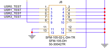
Pin1 - USR0TST GPIO28
Pin3 - USR1TST GPIO29
Pin5 - USR2TST GPIO30
Pin7 - USR3TST GPIO31
Pin9 - N/C (no connect)
All other pins are ground
A cable is included in the iRiser kit for access to these Signals.
Mirroring Example:
A scope is placed on USR0 and USR1 which is used to monitor POWER (12V) and PCIe RESET (PERST).
Mirroring can be set up using bit location or name, and the current configuration is displayed using the show gpio command. For example:
show gpio


 GPIO│31 24│23 16│15 8│7 0│

 ├─┬─┬─┬─┬─┬─┬─┬─┼─┬─┬─┬─┬─┬─┬─┬─┼─┬─┬─┬─┬─┬─┬─┬─┼─┬─┬─┬─┬─┬─┬─┬─┤

 │U│U│U│U│S│S│S│U│S│L│R│P│P│M│D│P│T│T│T│T│T│T│T│T│P│P│P│S│3│1│C│P│

 │S│S│S│S│B│B│B│S│T│E│F│L│L│F│U│R│x│x│x│x│x│x│x│x│1│0│W│M│V│2│L│E│

 │R│R│R│R│2│1│0│B│A│D│U│N│A│G│A│S│3│3│2│2│1│1│0│0│C│C│R│R│3│V│K│R│

 │3│2│1│0│G│G│G│D│T│E│E│E│E│E│L│N│P│N│P│N│P│N│P│N│L│L│D│S│ │ │R│S│

 │T│T│T│T│P│P│P│I│U│D│D│D│D│D│P│T│ │ │ │ │ │ │ │ │K│K│I│T│ │ │E│T│

 │S│S│S│S│I│I│I│S│S│S│S│S│S│S│T│L│ │ │ │ │ │ │ │ │L│L│S│L│ │ │Q│0│

 │T│T│T│T│O│O│O│L│L│F│F│F│F│F│L│ │ │ │ │ │ │ │ │ │ │ │ │ │ │ │L│L│

 ├─┼─┼─┼─┼─┼─┼─┼─┼─┼─┼─┼─┼─┼─┼─┼─┼─┼─┼─┼─┼─┼─┼─┼─┼─┼─┼─┼─┼─┼─┼─┼─┤

 │O│O│O│O│I│I│I│I│I│I│I│I│I│I│O│I│O│O│O│O│O│O│O│O│O│O│I│I│O│O│I│I│Dir:\[0x214\]0xf002ffcc

 ├─┼─┼─┼─┼─┼─┼─┼─┼─┼─┼─┼─┼─┼─┼─┼─┼─┼─┼─┼─┼─┼─┼─┼─┼─┼─┼─┼─┼─┼─┼─┼─┤

 │0│0│0│0│1│1│1│1│0│1│0│1│0│0│1│0│1│1│1│1│1│1│1│1│0│0│0│1│1│1│0│1│Val:\[0x200\]0x0f52ff1d

 └─┴─┴─┴─┴─┴─┴─┴─┴─┴─┴─┴─┴─┴─┴─┴─┴─┴─┴─┴─┴─┴─┴─┴─┴─┴─┴─┴─┴─┴─┴─┴─┘
In the above configuration, no mirroring has been established.
To set up the example of mirroring PERST to USR0TST and 12V to USR1TST, use the following commands (assumes iRiser5 is in slot 1):
 iriser -d \<slot\ mirror perst usr0

 INFO: Mirror\[0\] from perst0l\[0\] to usr0tst\[28\]
 iriser -d \<slot\ mirror 12v usr1

 INFO: Mirror\[1\] from 12v\[2\] to usr1tst\[29\]
[Issue the show GPIO command to inspect the mirror configuration:]{.mark}
iriser -d \<slot\ show gpio

 GPIO│31 24│23 16│15 8│7 0│

 ├─┬─┬─┬─┬─┬─┬─┬─┼─┬─┬─┬─┬─┬─┬─┬─┼─┬─┬─┬─┬─┬─┬─┬─┼─┬─┬─┬─┬─┬─┬─┬─┤

 │U│U│U│U│S│S│S│U│S│L│R│P│P│M│D│P│T│T│T│T│T│T│T│T│P│P│P│S│3│1│C│P│

 │S│S│S│S│B│B│B│S│T│E│F│L│L│F│U│R│x│x│x│x│x│x│x│x│1│0│W│M│V│2│L│E│

 │R│R│R│R│2│1│0│B│A│D│U│N│A│G│A│S│3│3│2│2│1│1│0│0│C│C│R│R│3│V│K│R│

 │3│2│1│0│G│G│G│D│T│E│E│E│E│E│L│N│P│N│P│N│P│N│P│N│L│L│D│S│ │ │R│S│

 │T│T│T│T│P│P│P│I│U│D│D│D│D│D│P│T│ │ │ │ │ │ │ │ │K│K│I│T│ │ │E│T│

 │S│S│S│S│I│I│I│S│S│S│S│S│S│S│T│L│ │ │ │ │ │ │ │ │L│L│S│L│ │ │Q│0│

 │T│T│T│T│O│O│O│L│L│F│F│F│F│F│L│ │ │ │ │ │ │ │ │ │ │ │ │ │ │ │L│L│

 ├─┼─┼─┼─┼─┼─┼─┼─┼─┼─┼─┼─┼─┼─┼─┼─┼─┼─┼─┼─┼─┼─┼─┼─┼─┼─┼─┼─┼─┼─┼─┼─┤

 │O│O│O│O│I│I│I│I│I│I│I│I│I│I│O│I│O│O│O│O│O│O│O│O│O│O│I│I│O│O│I│I│Dir:\[0x214\]0xf002ffcc

 ├─┼─┼─┼─┼─┼─┼─┼─┼─┼─┼─┼─┼─┼─┼─┼─┼─┼─┼─┼─┼─┼─┼─┼─┼─┼─┼─┼─┼─┼─┼─┼─┤

 │0│0│1│1│1│1│1│1│0│1│0│1│0│0│1│0│1│1│1│1│1│1│1│1│0│0│0│1│1│1│0│1│Val:\[0x200\]0x3f52ff1d

 └─┴─┴─┴─┴─┴─┴─┴─┴─┴─┴─┴─┴─┴─┴─┴─┴─┴─┴─┴─┴─┴─┴─┴─┴─┴─┴─┴─┴─┴─┴─┴─┘

 Mirroring GPIO: perst0l\[0\]-\usr0tst\[28\] 12v\[2\]-\usr1tst\[29\]
A show mirror has been added to the iRiser program to show any mirroring settings:
iriser -d <slot\ show mirror
If no signal mirroring is enabled, the output will read as this:
Slot[x] Mirror Bits are not configured.
For an example of mirroring PERST to USR0TST and CLKREQ to USR1TST, the show mirror output would look like this:
Mirroring GPIO: perst0l[0]-\usr0tst[28] clkreql[1]-\usr1tst[29].
Unmirror Command
To remove the mirroring, issue the unmirror command:
iriser -d <slot\ unmirror
Monitoring GPIO Signals with Mirroring
Once mirroring is established between the USRnTST Signals and any of the lower 28 GPIO bits, a change to the “from” bit will be reflected by the “to” bit for the purpose of externally monitoring that Signal.
Sequences and Actions
iRiser devices are programmed by means of loading Actions and Sequences of Actions to the device which are then executed by changing the specified GPIO Signals. Sequences are simply defined as groups of Actions that are linked together and either end in a “stop” (Sequence will run once and stop) or the index of another Action. If an Action points to the first Action in the Sequence, the Sequence will loop until the “stop” command is issued at the CLI.
If the Sequence is a loop and the system reboots, after the system comes back up, the Sequence will continue running. The blue status LED on the front of the iRiser will be blinking. If the Sequence is not a loop, after it stops running, the blue status LED on the front of the iRiser will stop blinking.
There are 128 “slots”, each of which can hold an Action, and a Sequence can be one or more Actions; up to 128 Actions can be defined in a Sequence.
Examples of a Sequence of Actions
To illustrate the use case of Actions and Sequences, see the two example test scenarios below. Note the following:
s = seconds
ms = milliseconds
us = microseconds
ns = nanoseconds
Example 1: Run Once and Stop Sequence
In this example, a user wants to see the effect of a glitch on PERST (reset) on the device under test exactly 5S after a clean power up. You may want to describe the following Actions:
Action 0 - Starting state: Deassert 12V Power, assert PERST, sleep 10 seconds
Action 1 - Assert 12v Power, sleep 250mS
Action 2 - Deassert PERST, sleep 5S
Action 3 - Assert PERST, sleep 100nS
Action 4 - Deassert PERST, and stop
Example 2: Run until Stopped (loop)
In this example, a user wants to repeat the test created above, but run it continuously every 15 seconds until stopped. Add an additional Action to the Actions above that loops back to Action 0.
Action 0 - Starting state: Deassert 12V Power, assert PERST, sleep 10 seconds
Action 1 - Assert 12v Power, sleep 250mS
Action 2 - deassert PERST, sleep 5S
Action 3 - assert PERST, sleep 100nS
Action 4 - deassert PERST, sleep 15S then return to Action 0
Defining Actions from CLI Command
The two examples above are built using the ‘iriser -d <slot\ edit action <action' command, which can be run from a single CLI command or interactively. First build the first example using the CLI command and then modify it interactively to demonstrate both methods.
Start with the iRiser device in Initial State:
iriser -d <slot\ init
Program the 5 actions described for Example 1:
#
# Commands to configure iRiser5 sequencer
#
iriser -d \<slot\ edit action 0 0xf002ffcd 0x0f52ff18 10.000000s 1 Deassert 12V Power assert PERST sleep 10 seconds
iriser -d \<slot\ edit action 1 0xf002ffcd 0x0f52ff1c 250.000000ms 2 Assert 12v Power sleep 250
iriser -d \<slot\ edit action 2 0xf002ffcd 0x0f52ff1d 5.000000s 3 Deassert PERST sleep 5S
iriser -d \<slot\ edit action 3 0xf002ffcd 0x0f52ff1c 100.000000ns 4 Assert PERST sleep 100nS
iriser -d \<slot\ edit action 4 0xf002ffcd 0x0f52ff1d 100.000000ns stop Deassert PERST sleep 100nS and stop sequencer
iriser -d <slot\ Edit Action
The iRiser is designed to be able to control Signals to a device under test at precise intervals. For example, an Action sequence could enable power to a device, 100mS later release PERST, and then 100mS after that assert PERST for 100nS and release it. Any combination of controlled Signals can be programmed in this manner.
iRiser -d <slot\ edit action <action number\ <direction\ <value\ <time\ <next action\ [name]
Where:
<slot\ - Physical slot number of the iRiser.
<action number\ - Action number, use show actions for list.
<direction\ - 32 bits of GPIO direction 1=output,0=input (use show gpio for Signal names).
Certain I/O direction bits may be locked by SANBlaze depending on configuration.
<value\ - 32 bits of GPIO Signal values.
All Signals MUST be defined, for a Signal that will not change on this Action you must specify same value as the preceding Action.
<time\ - Time specified as s (seconds), ms (milliseconds), us (microseconds), ns (nanoseconds) (e.g. 25.2ms).
Minimum time between Actions is 10nS.
<next\ - Next Action in the sequence.
If next = Usually current Action number +1 - Continue execution at that Action.
If next = “stop” - Stop execution (values in GPIO will remain at last Action values).
Valid range [0 - 127].
If next points to existing Action execution will jump to that Action.
If next points to an Action within the same Sequence, it will begin looping.
<name\ - Optional name for Action. These are stored in the .cfg and .sh files described elsewhere in this document. Special characters are only allowed in the Action name if you use quotation marks. Currently, 126 characters is the limit in length. Optionally, if not provided will be assigned to “Action <action number".
Note
When setting the name, it should be encased by a ‘ or “”. Otherwise, if the name has fields which can be interpreted as commands, the edit may fail. The quotes ensure that the string is treated as a string and not a set of separate commands.
Initializing the Action Memory
All Actions can be cleared with a single command.
WARNING - Use with caution.
iriser -d <slot\ init
For the scenario described above, start with power disabled and PERST enabled and wait 1s.
Show Current Actions
Once the Actions in Example 1 above have been programmed, you may show any one Action, all the Actions, or all the Actions in a given sequence with the following commands:
*iriser -d <slot\ show action <number*
iriser -d <slot\ show actions
*iriser -d <slot\ show sequence <number*
iriser -d <slot\ show sequences
For Example 1:
INFO: Action 0 Sequence 0

Direction: I/O (UC) user writable signal, i/o (LC) signal locked

GPIO│31 24│23 16│15 8│7 0│

├─┬─┬─┬─┬─┬─┬─┬─┼─┬─┬─┬─┬─┬─┬─┬─┼─┬─┬─┬─┬─┬─┬─┬─┼─┬─┬─┬─┬─┬─┬─┬─┤

│U│U│U│U│S│S│S│U│S│L│R│P│P│M│D│P│T│T│T│T│T│T│T│T│P│P│P│S│3│1│C│P│

│S│S│S│S│B│B│B│S│T│E│F│L│L│F│U│R│x│x│x│x│x│x│x│x│1│0│W│M│V│2│L│E│

│R│R│R│R│2│1│0│B│A│D│U│N│A│G│A│S│3│3│2│2│1│1│0│0│C│C│R│R│3│V│K│R│

│3│2│1│0│G│G│G│D│T│E│E│E│E│E│L│N│P│N│P│N│P│N│P│N│L│L│D│S│ │ │R│S│

│T│T│T│T│P│P│P│I│U│D│D│D│D│D│P│T│ │ │ │ │ │ │ │ │K│K│I│T│ │ │E│T│

│S│S│S│S│I│I│I│S│S│S│S│S│S│S│T│L│ │ │ │ │ │ │ │ │L│L│S│L│ │ │Q│0│

│T│T│T│T│O│O│O│L│L│F│F│F│F│F│L│ │ │ │ │ │ │ │ │ │ │ │ │ │ │ │L│L│

├─┼─┼─┼─┼─┼─┼─┼─┼─┼─┼─┼─┼─┼─┼─┼─┼─┼─┼─┼─┼─┼─┼─┼─┼─┼─┼─┼─┼─┼─┼─┼─┤

│O│O│O│O│I│I│I│I│I│I│I│I│I│I│O│I│O│O│O│O│O│O│O│O│O│O│I│I│O│O│I│O│Dir:\[0x804\]0xf002ffcd

Act ├─┼─┼─┼─┼─┼─┼─┼─┼─┼─┼─┼─┼─┼─┼─┼─┼─┼─┼─┼─┼─┼─┼─┼─┼─┼─┼─┼─┼─┼─┼─┼─┤Next│GPIO Value│Time

000 │0│0│0│0│1│1│1│1│0│1│0│1│0│0│1│0│1│1│1│1│1│1│1│1│0│0│0│1│1│0│0│0│ 001│0x0f52ff18│10.000000s

001 │0│0│0│0│1│1│1│1│0│1│0│1│0│0│1│0│1│1│1│1│1│1│1│1│0│0│0│1│1│1│0│0│ 002│0x0f52ff1c│250.000000ms

002 │0│0│0│0│1│1│1│1│0│1│0│1│0│0│1│0│1│1│1│1│1│1│1│1│0│0│0│1│1│1│0│1│ 003│0x0f52ff1d│5.000000s

003 │0│0│0│0│1│1│1│1│0│1│0│1│0│0│1│0│1│1│1│1│1│1│1│1│0│0│0│1│1│1│0│0│ 004│0x0f52ff1c│100.000000ns

004 │0│0│0│0│1│1│1│1│0│1│0│1│0│0│1│0│1│1│1│1│1│1│1│1│0│0│0│1│1│1│0│1│ 004│0x0f52ff1d│100.000000ns Stop
Starting a Sequence
Sequences are groups of Actions that terminate (stop) or loop (jump back to start). Sequence numbers begin at zero and are assigned automatically. You cannot re-number Sequences. To find all currently programmed Sequences, use the show Sequences command.
Start the Sequence defined in Example 1 above with the command:
iriser -d <slot\ start sequence 0
Because the Sequence is set to stop, using the show Sequence 0 command will first show the Sequence as running, and then stopped.
What happens while the Sequence is running?
Monitoring your device using the SANBlaze built-in “tracing” will show the NVMe activity as the Sequence executes.
Monitor Activity with Tracing
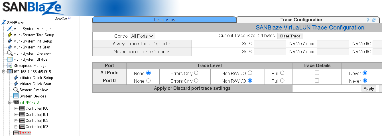
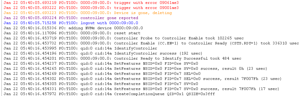
Monitoring Activity with sb_logger
A CLI program sb_logger is provided with all SANBlaze systems, which continuously monitors all relevant log files on the system.
It is common (and best) practice to leave the sb_logger program running in a CLI window while executing Sequences to see how the Sequence is affecting your device.
The following is an example of sb_logger session:
sb_logger

==\ /virtualun/log/iriser \<==
Mon Jan 22 05:45:31 2024: INFO: Starting sequencer at action location action=0

==\ /virtualun/log/sb_i2c2 \<==
Mon Jan 22 05:45:31 2024: sb_i2c2 -d 0 -f STATUS_BLUE_LED_L -w 3 -q

==\ /var/log/messages \<==
Jan 22 05:45:31 dt5-i915 kernel: \[81541.435244\] nvme: DPC: link to bus 09 is now DOWN
Jan 22 05:45:31 dt5-i915 kernel: \[81541.435250\] nvme: HP: Slot(0): status 0108/4001 for bus 09
Jan 22 05:45:31 dt5-i915 kernel: \[81541.435252\] nvme: HP: Slot(0): Presence Not Detected on bus 09
Jan 22 05:45:31 dt5-i915 kernel: \[81541.435253\] nvme: HP: Slot(0): Link Down on bus 09
Jan 22 05:45:31 dt5-i915 kernel: \[81541.435258\] nvme: DPC status 0009 for bus 09
Jan 22 05:45:31 dt5-i915 kernel: \[81541.435267\] nvme: HP: Slot(0): link to bus 09 is DOWN
Jan 22 05:45:31 dt5-i915 kernel: \[81541.435270\] nvme_vlun_hp_down@15229: 0000:04:08.0 0000:09:00.0
Jan 22 05:45:31 dt5-i915 kernel: \[81541.435272\] nvme_vlun_hp_remove@15212: echo 1 \ /sys/bus/pci/devices/0000:09:00.0/remove
Jan 22 05:45:31 dt5-i915 kernel: \[81541.435291\] remove PCI device 0000:09:00.0 start
Jan 22 05:45:31 dt5-i915 kernel: \[81541.435292\] pci_stop_bus_device@101: 0000:09:00.0: ffff88107241d800 0000:09
Jan 22 05:45:31 dt5-i915 kernel: \[81541.435297\] nvme: 0000:09:00.0: code 6
Jan 22 05:45:31 dt5-i915 kernel: \[81541.435304\] nvme_remove@7993: 0000:09:00.0: cfg rd 0004 ffff
Jan 22 05:45:31 dt5-i915 kernel: \[81541.435305\] nvme_remove@7994: 0000:09:00.0: cfg rd 0006 ffff
Jan 22 05:45:31 dt5-i915 kernel: \[81541.435312\] 0000:09:00.0: trigger with error 09061ae3
Jan 22 05:45:31 dt5-i915 kernel: \[81541.435314\] 0000:09:00.0: trigger with error 09001ae3
Jan 22 05:45:31 dt5-i915 kernel: \[81541.435315\] 0000:09:00.0: Device is gone, deleting
Jan 22 05:45:31 dt5-i915 kernel: \[81541.435317\] pci 0000:09:00.0: vendor/device ffffffff
Jan 22 05:45:31 dt5-i915 kernel: \[81541.435321\] nvme_dev_dis@6091: 0000:09:00.0: rd 1c ffffffff
Jan 22 05:45:31 dt5-i915 kernel: \[81541.435531\] nvme_disable_admin_queue@4253: 0000:09:00.0: rd 00 ffffffffffffffff
Jan 22 05:45:31 dt5-i915 kernel: \[81541.435552\] nvme_pci_disable@6055: 0000:09:00.0: cfg rd 0004 ffff
Jan 22 05:45:31 dt5-i915 kernel: \[81541.456799\] nvme: removing device 0000:09:00.0
Jan 22 05:45:31 dt5-i915 kernel: \[81541.457152\] nvme_pci_free_ctrl@6181: dev\<ffff88106019e000\ pdev\<ffff880f6e8d6000\
Jan 22 05:45:31 dt5-i915 kernel: \[81541.457153\] nvme_pci_free_ctrl@6190: dev\<ffff88106019e000\
Jan 22 05:45:31 dt5-i915 kernel: \[81541.457166\] nvme: 0000:09:00.0: code 7
Jan 22 05:45:31 dt5-i915 kernel: \[81541.457174\] \_pci_remove_bus_device@136: 0000:09:00.0: ffff88107241d800 0000:09
Jan 22 05:45:31 dt5-i915 kernel: \[81541.457174\] nvme: 0000:09:00.0: code 2
Jan 22 05:45:31 dt5-i915 kernel: \[81541.457183\] nvme: 0000:09:00.0: code 3
Jan 22 05:45:31 dt5-i915 kernel: \[81541.457193\] remove PCI device 0000:09:00.0 end
Jan 22 05:45:31 dt5-i915 kernel: \[81541.457196\] pci: free ffff880f6e8d6000 0000:09:00.0 1bb1:5018
Interactive Action Editing
An interactive method for editing Actions is built into the system. Editing Actions interactively provides built-in help and makes the process easier to visualize.
To illustrate this, we will modify Example 1 above using interactive edits to change the Sequence from a “run once and stop” to a “loop” Sequence, which then runs until stopped by the iriser -d <slot\ stop command.
Starting Point
As shown above, we created Sequence 0 which runs once and stops. For example:
INFO: Action 0 Sequence 0

Direction: I/O (UC) user writable signal, i/o (LC) signal locked

GPIO│31 24│23 16│15 8│7 0│

├─┬─┬─┬─┬─┬─┬─┬─┼─┬─┬─┬─┬─┬─┬─┬─┼─┬─┬─┬─┬─┬─┬─┬─┼─┬─┬─┬─┬─┬─┬─┬─┤

│U│U│U│U│S│S│S│U│S│L│R│P│P│M│D│P│T│T│T│T│T│T│T│T│P│P│P│S│3│1│C│P│

│S│S│S│S│B│B│B│S│T│E│F│L│L│F│U│R│x│x│x│x│x│x│x│x│1│0│W│M│V│2│L│E│

│R│R│R│R│2│1│0│B│A│D│U│N│A│G│A│S│3│3│2│2│1│1│0│0│C│C│R│R│3│V│K│R│

│3│2│1│0│G│G│G│D│T│E│E│E│E│E│L│N│P│N│P│N│P│N│P│N│L│L│D│S│ │ │R│S│

│T│T│T│T│P│P│P│I│U│D│D│D│D│D│P│T│ │ │ │ │ │ │ │ │K│K│I│T│ │ │E│T│

│S│S│S│S│I│I│I│S│S│S│S│S│S│S│T│L│ │ │ │ │ │ │ │ │L│L│S│L│ │ │Q│0│

│T│T│T│T│O│O│O│L│L│F│F│F│F│F│L│ │ │ │ │ │ │ │ │ │ │ │ │ │ │ │L│L│

├─┼─┼─┼─┼─┼─┼─┼─┼─┼─┼─┼─┼─┼─┼─┼─┼─┼─┼─┼─┼─┼─┼─┼─┼─┼─┼─┼─┼─┼─┼─┼─┤

│O│O│O│O│I│I│I│I│I│I│I│I│I│I│O│I│O│O│O│O│O│O│O│O│O│O│I│I│O│O│I│O│Dir:\[0x804\]0xf002ffcd

Act ├─┼─┼─┼─┼─┼─┼─┼─┼─┼─┼─┼─┼─┼─┼─┼─┼─┼─┼─┼─┼─┼─┼─┼─┼─┼─┼─┼─┼─┼─┼─┼─┤Next│GPIO Value│Time

000 │0│0│0│0│1│1│1│1│0│1│0│1│0│0│1│0│1│1│1│1│1│1│1│1│0│0│0│1│1│0│0│0│ 001│0x0f52ff18│10.000000s

001 │0│0│0│0│1│1│1│1│0│1│0│1│0│0│1│0│1│1│1│1│1│1│1│1│0│0│0│1│1│1│0│0│ 002│0x0f52ff1c│250.000000ms

002 │0│0│0│0│1│1│1│1│0│1│0│1│0│0│1│0│1│1│1│1│1│1│1│1│0│0│0│1│1│1│0│1│ 003│0x0f52ff1d│5.000000s

003 │0│0│0│0│1│1│1│1│0│1│0│1│0│0│1│0│1│1│1│1│1│1│1│1│0│0│0│1│1│1│0│0│ 004│0x0f52ff1c│100.000000ns

004 │0│0│0│0│1│1│1│1│0│1│0│1│0│0│1│0│1│1│1│1│1│1│1│1│0│0│0│1│1│1│0│1│ 004│0x0f52ff1d│100.000000ns Stop

└─┴─┴─┴─┴─┴─┴─┴─┴─┴─┴─┴─┴─┴─┴─┴─┴─┴─┴─┴─┴─┴─┴─┴─┴─┴─┴─┴─┴─┴─┴─┴─┘

Sequencer: Stopped
We modify Action 4 to sleep for 10 seconds and then loop back to Action 0, thus looping indefinitely until stopped.
The interactive session is shown below:
iriser -d \<slot\ edit action 4

Prior action points to me, use GPIO_dir from prior action

Direction: I/O (UC) user writable signal, i/o (LC) signal locked

GPIO│31 24│23 16│15 8│7 0│

├─┬─┬─┬─┬─┬─┬─┬─┼─┬─┬─┬─┬─┬─┬─┬─┼─┬─┬─┬─┬─┬─┬─┬─┼─┬─┬─┬─┬─┬─┬─┬─┤

│U│U│U│U│S│S│S│U│S│L│R│P│P│M│D│P│T│T│T│T│T│T│T│T│P│P│P│S│3│1│C│P│

│S│S│S│S│B│B│B│S│T│E│F│L│L│F│U│R│x│x│x│x│x│x│x│x│1│0│W│M│V│2│L│E│

│R│R│R│R│2│1│0│B│A│D│U│N│A│G│A│S│3│3│2│2│1│1│0│0│C│C│R│R│3│V│K│R│

│3│2│1│0│G│G│G│D│T│E│E│E│E│E│L│N│P│N│P│N│P│N│P│N│L│L│D│S│ │ │R│S│

│T│T│T│T│P│P│P│I│U│D│D│D│D│D│P│T│ │ │ │ │ │ │ │ │K│K│I│T│ │ │E│T│

│S│S│S│S│I│I│I│S│S│S│S│S│S│S│T│L│ │ │ │ │ │ │ │ │L│L│S│L│ │ │Q│0│

│T│T│T│T│O│O│O│L│L│F│F│F│F│F│L│ │ │ │ │ │ │ │ │ │ │ │ │ │ │ │L│L│

├─┼─┼─┼─┼─┼─┼─┼─┼─┼─┼─┼─┼─┼─┼─┼─┼─┼─┼─┼─┼─┼─┼─┼─┼─┼─┼─┼─┼─┼─┼─┼─┤

│O│O│O│O│I│I│I│I│I│I│I│I│I│I│O│I│O│O│O│O│O│O│O│O│O│O│I│I│O│O│I│O│Dir:\[0x844\]0xf002ffcd

Act ├─┼─┼─┼─┼─┼─┼─┼─┼─┼─┼─┼─┼─┼─┼─┼─┼─┼─┼─┼─┼─┼─┼─┼─┼─┼─┼─┼─┼─┼─┼─┼─┤Next│GPIO Value│Time

004 │0│0│0│0│1│1│1│1│0│1│0│1│0│0│1│0│1│1│1│1│1│1│1│1│0│0│0│1│1│1│0│0│ 004│0x0f52ff1c│100.000000ns

└─┴─┴─┴─┴─┴─┴─┴─┴─┴─┴─┴─┴─┴─┴─┴─┴─┴─┴─┴─┴─┴─┴─┴─┴─┴─┴─┴─┴─┴─┴─┴─┘
Enter 32bit hex or bit name/number or h for help. DIRECTION:[0xf002ffcd]:
We do not want to change DIRECTION and therefore we type <cr\ to take the default which advances the editor to ask for VALUE.
Direction: I/O (UC) user writable signal, i/o (LC) signal locked
GPIO│31 24│23 16│15 8│7 0│

├─┬─┬─┬─┬─┬─┬─┬─┼─┬─┬─┬─┬─┬─┬─┬─┼─┬─┬─┬─┬─┬─┬─┬─┼─┬─┬─┬─┬─┬─┬─┬─┤

│U│U│U│U│S│S│S│U│S│L│R│P│P│M│D│P│T│T│T│T│T│T│T│T│P│P│P│S│3│1│C│P│

│S│S│S│S│B│B│B│S│T│E│F│L│L│F│U│R│x│x│x│x│x│x│x│x│1│0│W│M│V│2│L│E│

│R│R│R│R│2│1│0│B│A│D│U│N│A│G│A│S│3│3│2│2│1│1│0│0│C│C│R│R│3│V│K│R│

│3│2│1│0│G│G│G│D│T│E│E│E│E│E│L│N│P│N│P│N│P│N│P│N│L│L│D│S│ │ │R│S│

│T│T│T│T│P│P│P│I│U│D│D│D│D│D│P│T│ │ │ │ │ │ │ │ │K│K│I│T│ │ │E│T│

│S│S│S│S│I│I│I│S│S│S│S│S│S│S│T│L│ │ │ │ │ │ │ │ │L│L│S│L│ │ │Q│0│

│T│T│T│T│O│O│O│L│L│F│F│F│F│F│L│ │ │ │ │ │ │ │ │ │ │ │ │ │ │ │L│L│

├─┼─┼─┼─┼─┼─┼─┼─┼─┼─┼─┼─┼─┼─┼─┼─┼─┼─┼─┼─┼─┼─┼─┼─┼─┼─┼─┼─┼─┼─┼─┼─┤

│O│O│O│O│I│I│I│I│I│I│I│I│I│I│O│I│O│O│O│O│O│O│O│O│O│O│I│I│O│O│I│O│Dir:\[0x844\]0xf002ffcd

Act ├─┼─┼─┼─┼─┼─┼─┼─┼─┼─┼─┼─┼─┼─┼─┼─┼─┼─┼─┼─┼─┼─┼─┼─┼─┼─┼─┼─┼─┼─┼─┼─┤Next│GPIO Value│Time

004 │0│0│0│0│1│1│1│1│0│1│0│1│0│0│1│0│1│1│1│1│1│1│1│1│0│0│0│1│1│1│0│0│ 000│0x0f52ff1c│10.000000s

└─┴─┴─┴─┴─┴─┴─┴─┴─┴─┴─┴─┴─┴─┴─┴─┴─┴─┴─┴─┴─┴─┴─┴─┴─┴─┴─┴─┴─┴─┴─┴─┘

Prior action points to me, use GPIO_out from prior action

Direction: I/O (UC) user writable signal, i/o (LC) signal locked

GPIO│31 24│23 16│15 8│7 0│

├─┬─┬─┬─┬─┬─┬─┬─┼─┬─┬─┬─┬─┬─┬─┬─┼─┬─┬─┬─┬─┬─┬─┬─┼─┬─┬─┬─┬─┬─┬─┬─┤

│U│U│U│U│S│S│S│U│S│L│R│P│P│M│D│P│T│T│T│T│T│T│T│T│P│P│P│S│3│1│C│P│

│S│S│S│S│B│B│B│S│T│E│F│L│L│F│U│R│x│x│x│x│x│x│x│x│1│0│W│M│V│2│L│E│

│R│R│R│R│2│1│0│B│A│D│U│N│A│G│A│S│3│3│2│2│1│1│0│0│C│C│R│R│3│V│K│R│

│3│2│1│0│G│G│G│D│T│E│E│E│E│E│L│N│P│N│P│N│P│N│P│N│L│L│D│S│ │ │R│S│

│T│T│T│T│P│P│P│I│U│D│D│D│D│D│P│T│ │ │ │ │ │ │ │ │K│K│I│T│ │ │E│T│

│S│S│S│S│I│I│I│S│S│S│S│S│S│S│T│L│ │ │ │ │ │ │ │ │L│L│S│L│ │ │Q│0│

│T│T│T│T│O│O│O│L│L│F│F│F│F│F│L│ │ │ │ │ │ │ │ │ │ │ │ │ │ │ │L│L│

├─┼─┼─┼─┼─┼─┼─┼─┼─┼─┼─┼─┼─┼─┼─┼─┼─┼─┼─┼─┼─┼─┼─┼─┼─┼─┼─┼─┼─┼─┼─┼─┤

│O│O│O│O│I│I│I│I│I│I│I│I│I│I│O│I│O│O│O│O│O│O│O│O│O│O│I│I│O│O│I│O│Dir:\[0x844\]0xf002ffcd

Act ├─┼─┼─┼─┼─┼─┼─┼─┼─┼─┼─┼─┼─┼─┼─┼─┼─┼─┼─┼─┼─┼─┼─┼─┼─┼─┼─┼─┼─┼─┼─┼─┤Next│GPIO Value│Time

004 │0│0│0│0│1│1│1│1│0│1│0│1│0│0│1│0│1│1│1│1│1│1│1│1│0│0│0│1│1│1│0│0│ 004│0x0f52ff1c│100.000000ns

└─┴─┴─┴─┴─┴─┴─┴─┴─┴─┴─┴─┴─┴─┴─┴─┴─┴─┴─┴─┴─┴─┴─┴─┴─┴─┴─┴─┴─┴─┴─┴─┘

Enter 32bit hex or bit name/number or h for help. VALUE:\[0x0f52ff1c\]: perst
We want to leave PERST de-asserted, and see that the default for Action 4 is zero (asserted). At this point we have three options in the editor. We can toggle a single bit by name, by bit location, or we can write the entire 32bit output value. We choose toggle by name. The three input options are as follows:
Change bit value by name - perst
Change bit value by location - 0
Change entire GPIO register - 0x0f52ff1d
Direction: I/O (UC) user writable signal, i/o (LC) signal locked

GPIO│31 24│23 16│15 8│7 0│

├─┬─┬─┬─┬─┬─┬─┬─┼─┬─┬─┬─┬─┬─┬─┬─┼─┬─┬─┬─┬─┬─┬─┬─┼─┬─┬─┬─┬─┬─┬─┬─┤

│U│U│U│U│S│S│S│U│S│L│R│P│P│M│D│P│T│T│T│T│T│T│T│T│P│P│P│S│3│1│C│P│

│S│S│S│S│B│B│B│S│T│E│F│L│L│F│U│R│x│x│x│x│x│x│x│x│1│0│W│M│V│2│L│E│

│R│R│R│R│2│1│0│B│A│D│U│N│A│G│A│S│3│3│2│2│1│1│0│0│C│C│R│R│3│V│K│R│

│3│2│1│0│G│G│G│D│T│E│E│E│E│E│L│N│P│N│P│N│P│N│P│N│L│L│D│S│ │ │R│S│

│T│T│T│T│P│P│P│I│U│D│D│D│D│D│P│T│ │ │ │ │ │ │ │ │K│K│I│T│ │ │E│T│

│S│S│S│S│I│I│I│S│S│S│S│S│S│S│T│L│ │ │ │ │ │ │ │ │L│L│S│L│ │ │Q│0│

│T│T│T│T│O│O│O│L│L│F│F│F│F│F│L│ │ │ │ │ │ │ │ │ │ │ │ │ │ │ │L│L│

├─┼─┼─┼─┼─┼─┼─┼─┼─┼─┼─┼─┼─┼─┼─┼─┼─┼─┼─┼─┼─┼─┼─┼─┼─┼─┼─┼─┼─┼─┼─┼─┤

│O│O│O│O│I│I│I│I│I│I│I│I│I│I│O│I│O│O│O│O│O│O│O│O│O│O│I│I│O│O│I│O│Dir:\[0x844\]0xf002ffcd

Act ├─┼─┼─┼─┼─┼─┼─┼─┼─┼─┼─┼─┼─┼─┼─┼─┼─┼─┼─┼─┼─┼─┼─┼─┼─┼─┼─┼─┼─┼─┼─┼─┤Next│GPIO Value│Time

004 │0│0│0│0│1│1│1│1│0│1│0│1│0│0│1│0│1│1│1│1│1│1│1│1│0│0│0│1│1│1│0│1│ 000│0x0f52ff1d│10.000000s

└─┴─┴─┴─┴─┴─┴─┴─┴─┴─┴─┴─┴─┴─┴─┴─┴─┴─┴─┴─┴─┴─┴─┴─┴─┴─┴─┴─┴─┴─┴─┴─┘

Enter 32bit hex or bit name/number or h for help. VALUE:\[0x0f52ff1d\]:
You can toggle as many bits as you want using this method. When satisfied with the VALUE bits, simply accept the current value using <cr, and the editor will move on to ask for TIME.
Direction: I/O (UC) user writable signal, i/o (LC) signal locked

GPIO│31 24│23 16│15 8│7 0│

├─┬─┬─┬─┬─┬─┬─┬─┼─┬─┬─┬─┬─┬─┬─┬─┼─┬─┬─┬─┬─┬─┬─┬─┼─┬─┬─┬─┬─┬─┬─┬─┤

│U│U│U│U│S│S│S│U│S│L│R│P│P│M│D│P│T│T│T│T│T│T│T│T│P│P│P│S│3│1│C│P│

│S│S│S│S│B│B│B│S│T│E│F│L│L│F│U│R│x│x│x│x│x│x│x│x│1│0│W│M│V│2│L│E│

│R│R│R│R│2│1│0│B│A│D│U│N│A│G│A│S│3│3│2│2│1│1│0│0│C│C│R│R│3│V│K│R│

│3│2│1│0│G│G│G│D│T│E│E│E│E│E│L│N│P│N│P│N│P│N│P│N│L│L│D│S│ │ │R│S│

│T│T│T│T│P│P│P│I│U│D│D│D│D│D│P│T│ │ │ │ │ │ │ │ │K│K│I│T│ │ │E│T│

│S│S│S│S│I│I│I│S│S│S│S│S│S│S│T│L│ │ │ │ │ │ │ │ │L│L│S│L│ │ │Q│0│

│T│T│T│T│O│O│O│L│L│F│F│F│F│F│L│ │ │ │ │ │ │ │ │ │ │ │ │ │ │ │L│L│

├─┼─┼─┼─┼─┼─┼─┼─┼─┼─┼─┼─┼─┼─┼─┼─┼─┼─┼─┼─┼─┼─┼─┼─┼─┼─┼─┼─┼─┼─┼─┼─┤

│O│O│O│O│I│I│I│I│I│I│I│I│I│I│O│I│O│O│O│O│O│O│O│O│O│O│I│I│O│O│I│O│Dir:\[0x844\]0xf002ffcd

Act ├─┼─┼─┼─┼─┼─┼─┼─┼─┼─┼─┼─┼─┼─┼─┼─┼─┼─┼─┼─┼─┼─┼─┼─┼─┼─┼─┼─┼─┼─┼─┼─┤Next│GPIO Value│Time

004 │0│0│0│0│1│1│1│1│0│1│0│1│0│0│1│0│1│1│1│1│1│1│1│1│0│0│0│1│1│1│0│1│ 000│0x0f52ff1d│10.000000s

└─┴─┴─┴─┴─┴─┴─┴─┴─┴─┴─┴─┴─┴─┴─┴─┴─┴─┴─┴─┴─┴─┴─┴─┴─┴─┴─┴─┴─┴─┴─┴─┘

Specify time in s, ms, us, ns (e.g. 25.2ms). Time \[10.00s\]:
We want to leave the device under test (DUT) time to stabilize before starting the loop over, so we enter a reasonable time of 10 seconds. The editor will move to ask for label.
Note
The minimum time between Actions, and therefore the minimum time between changing the state of a Signal is 10ns. If you enter a value less than 10ns you will be prompted to correct.
Sequence label for Action 4 [Action 4]: Sleep 10s and loop to action 0
We reject the default label of “Action 4” and provide our own label. The editor moves to ask for “next action”.
Next Action (0=loop, s=stop, w=write, q=quit) [ 5]: 0
The editor provides us with four choices and a default. The default is Action + 1, so in our case 5. If you take the default, the editing session will continue and you can define Action 5, but we want to loop at this point, so select 0. The “loop” index will be the first index in the current Sequence and may not be zero.
Next Action Options
loop - An Action within the Sequence will loop back into the Sequence and run until manually stopped. The loop default is the first Action in the current Sequence.
s - Stop Sequence leaving Signal states at the currently defined I/O and value.
w - Write the changes to the given Action or Actions and exit interactive editor.
q - Abandon the changes to the give Action or Actions and quit the interactive editor.
At this point entering “s” will make the current Action last and stop the Sequencer. Be sure to leave all GPIO bits in the state you wish them to remain once the Sequence stops.
For example, if you leave power (12V) at zero or PERST at 0 your DUT will not be accessible.
Direction: I/O (UC) user writable signal, i/o (LC) signal locked

GPIO│31 24│23 16│15 8│7 0│

├─┬─┬─┬─┬─┬─┬─┬─┼─┬─┬─┬─┬─┬─┬─┬─┼─┬─┬─┬─┬─┬─┬─┬─┼─┬─┬─┬─┬─┬─┬─┬─┤

│U│U│U│U│S│S│S│U│S│L│R│P│P│M│D│P│T│T│T│T│T│T│T│T│P│P│P│S│3│1│C│P│

│S│S│S│S│B│B│B│S│T│E│F│L│L│F│U│R│x│x│x│x│x│x│x│x│1│0│W│M│V│2│L│E│

│R│R│R│R│2│1│0│B│A│D│U│N│A│G│A│S│3│3│2│2│1│1│0│0│C│C│R│R│3│V│K│R│

│3│2│1│0│G│G│G│D│T│E│E│E│E│E│L│N│P│N│P│N│P│N│P│N│L│L│D│S│ │ │R│S│

│T│T│T│T│P│P│P│I│U│D│D│D│D│D│P│T│ │ │ │ │ │ │ │ │K│K│I│T│ │ │E│T│

│S│S│S│S│I│I│I│S│S│S│S│S│S│S│T│L│ │ │ │ │ │ │ │ │L│L│S│L│ │ │Q│0│

│T│T│T│T│O│O│O│L│L│F│F│F│F│F│L│ │ │ │ │ │ │ │ │ │ │ │ │ │ │ │L│L│

├─┼─┼─┼─┼─┼─┼─┼─┼─┼─┼─┼─┼─┼─┼─┼─┼─┼─┼─┼─┼─┼─┼─┼─┼─┼─┼─┼─┼─┼─┼─┼─┤

│O│O│O│O│I│I│I│I│I│I│I│I│I│I│O│I│O│O│O│O│O│O│O│O│O│O│I│I│O│O│I│O│Dir:\[0x844\]0xf002ffcd

Act ├─┼─┼─┼─┼─┼─┼─┼─┼─┼─┼─┼─┼─┼─┼─┼─┼─┼─┼─┼─┼─┼─┼─┼─┼─┼─┼─┼─┼─┼─┼─┼─┤Next│GPIO Value│Time

004 │0│0│0│0│1│1│1│1│0│1│0│1│0│0│1│0│1│1│1│1│1│1│1│1│0│0│0│1│1│1│0│1│ 000│0x0f52ff1d│10.000000s

└─┴─┴─┴─┴─┴─┴─┴─┴─┴─┴─┴─┴─┴─┴─┴─┴─┴─┴─┴─┴─┴─┴─┴─┴─┴─┴─┴─┴─┴─┴─┴─┘

Sequencer: Stopped

INFO: Action edit complete, use iriser -d \<slot\ start action 4 to start

\[root@dt5-i915 iRiser\]# iriser -d \<slot\ show sequence 0

INFO: Action 0 Sequence 0

Direction: I/O (UC) user writable signal, i/o (LC) signal locked

GPIO│31 24│23 16│15 8│7 0│

├─┬─┬─┬─┬─┬─┬─┬─┼─┬─┬─┬─┬─┬─┬─┬─┼─┬─┬─┬─┬─┬─┬─┬─┼─┬─┬─┬─┬─┬─┬─┬─┤

│U│U│U│U│S│S│S│U│S│L│R│P│P│M│D│P│T│T│T│T│T│T│T│T│P│P│P│S│3│1│C│P│

│S│S│S│S│B│B│B│S│T│E│F│L│L│F│U│R│x│x│x│x│x│x│x│x│1│0│W│M│V│2│L│E│

│R│R│R│R│2│1│0│B│A│D│U│N│A│G│A│S│3│3│2│2│1│1│0│0│C│C│R│R│3│V│K│R│

│3│2│1│0│G│G│G│D│T│E│E│E│E│E│L│N│P│N│P│N│P│N│P│N│L│L│D│S│ │ │R│S│

│T│T│T│T│P│P│P│I│U│D│D│D│D│D│P│T│ │ │ │ │ │ │ │ │K│K│I│T│ │ │E│T│

│S│S│S│S│I│I│I│S│S│S│S│S│S│S│T│L│ │ │ │ │ │ │ │ │L│L│S│L│ │ │Q│0│

│T│T│T│T│O│O│O│L│L│F│F│F│F│F│L│ │ │ │ │ │ │ │ │ │ │ │ │ │ │ │L│L│

├─┼─┼─┼─┼─┼─┼─┼─┼─┼─┼─┼─┼─┼─┼─┼─┼─┼─┼─┼─┼─┼─┼─┼─┼─┼─┼─┼─┼─┼─┼─┼─┤

│O│O│O│O│I│I│I│I│I│I│I│I│I│I│O│I│O│O│O│O│O│O│O│O│O│O│I│I│O│O│I│O│Dir:\[0x804\]0xf002ffcd

Act ├─┼─┼─┼─┼─┼─┼─┼─┼─┼─┼─┼─┼─┼─┼─┼─┼─┼─┼─┼─┼─┼─┼─┼─┼─┼─┼─┼─┼─┼─┼─┼─┤Next│GPIO Value│Time

000 │0│0│0│0│1│1│1│1│0│1│0│1│0│0│1│0│1│1│1│1│1│1│1│1│0│0│0│1│1│0│0│0│ 001│0x0f52ff18│10.000000s

001 │0│0│0│0│1│1│1│1│0│1│0│1│0│0│1│0│1│1│1│1│1│1│1│1│0│0│0│1│1│1│0│0│ 002│0x0f52ff1c│250.000000ms

002 │0│0│0│0│1│1│1│1│0│1│0│1│0│0│1│0│1│1│1│1│1│1│1│1│0│0│0│1│1│1│0│1│ 003│0x0f52ff1d│5.000000s

003 │0│0│0│0│1│1│1│1│0│1│0│1│0│0│1│0│1│1│1│1│1│1│1│1│0│0│0│1│1│1│0│0│ 004│0x0f52ff1c│100.000000ns

004 │0│0│0│0│1│1│1│1│0│1│0│1│0│0│1│0│1│1│1│1│1│1│1│1│0│0│0│1│1│1│0│1│ 000│0x0f52ff1d│10.000000s

└─┴─┴─┴─┴─┴─┴─┴─┴─┴─┴─┴─┴─┴─┴─┴─┴─┴─┴─┴─┴─┴─┴─┴─┴─┴─┴─┴─┴─┴─┴─┴─┘

Sequencer: Stopped
Now when you start sequence 0 it will continue running and will loop back, turn off the DUT and start again.
iriser -d \<slot\ start sequence 0

iriser -d \<slot\ show sequence 0

INFO: Action 0 Sequence 0

Direction: I/O (UC) user writable signal, i/o (LC) signal locked

GPIO│31 24│23 16│15 8│7 0│

├─┬─┬─┬─┬─┬─┬─┬─┼─┬─┬─┬─┬─┬─┬─┬─┼─┬─┬─┬─┬─┬─┬─┬─┼─┬─┬─┬─┬─┬─┬─┬─┤

│U│U│U│U│S│S│S│U│S│L│R│P│P│M│D│P│T│T│T│T│T│T│T│T│P│P│P│S│3│1│C│P│

│S│S│S│S│B│B│B│S│T│E│F│L│L│F│U│R│x│x│x│x│x│x│x│x│1│0│W│M│V│2│L│E│

│R│R│R│R│2│1│0│B│A│D│U│N│A│G│A│S│3│3│2│2│1│1│0│0│C│C│R│R│3│V│K│R│

│3│2│1│0│G│G│G│D│T│E│E│E│E│E│L│N│P│N│P│N│P│N│P│N│L│L│D│S│ │ │R│S│

│T│T│T│T│P│P│P│I│U│D│D│D│D│D│P│T│ │ │ │ │ │ │ │ │K│K│I│T│ │ │E│T│

│S│S│S│S│I│I│I│S│S│S│S│S│S│S│T│L│ │ │ │ │ │ │ │ │L│L│S│L│ │ │Q│0│

│T│T│T│T│O│O│O│L│L│F│F│F│F│F│L│ │ │ │ │ │ │ │ │ │ │ │ │ │ │ │L│L│

├─┼─┼─┼─┼─┼─┼─┼─┼─┼─┼─┼─┼─┼─┼─┼─┼─┼─┼─┼─┼─┼─┼─┼─┼─┼─┼─┼─┼─┼─┼─┼─┤

│O│O│O│O│I│I│I│I│I│I│I│I│I│I│O│I│O│O│O│O│O│O│O│O│O│O│I│I│O│O│I│O│Dir:\[0x804\]0xf002ffcd

Act ├─┼─┼─┼─┼─┼─┼─┼─┼─┼─┼─┼─┼─┼─┼─┼─┼─┼─┼─┼─┼─┼─┼─┼─┼─┼─┼─┼─┼─┼─┼─┼─┤Next│GPIO Value│Time

000 │0│0│0│0│1│1│1│1│0│1│0│1│0│0│1│0│1│1│1│1│1│1│1│1│0│0│0│1│1│0│0│0│ 001│0x0f52ff18│10.000000s

001 │0│0│0│0│1│1│1│1│0│1│0│1│0│0│1│0│1│1│1│1│1│1│1│1│0│0│0│1│1│1│0│0│ 002│0x0f52ff1c│250.000000ms

002 │0│0│0│0│1│1│1│1│0│1│0│1│0│0│1│0│1│1│1│1│1│1│1│1│0│0│0│1│1│1│0│1│ 003│0x0f52ff1d│5.000000s

003 │0│0│0│0│1│1│1│1│0│1│0│1│0│0│1│0│1│1│1│1│1│1│1│1│0│0│0│1│1│1│0│0│ 004│0x0f52ff1c│100.000000ns

004 │0│0│0│0│1│1│1│1│0│1│0│1│0│0│1│0│1│1│1│1│1│1│1│1│0│0│0│1│1│1│0│1│ 000│0x0f52ff1d│10.000000s

└─┴─┴─┴─┴─┴─┴─┴─┴─┴─┴─┴─┴─┴─┴─┴─┴─┴─┴─┴─┴─┴─┴─┴─┴─┴─┴─┴─┴─┴─┴─┴─┘

Sequencer: Running

iriser -d \<slot\ show sequences
Additional notes on Adding new Actions
If there are no Sequences currently on the iRiser, the IO direction and IO Value hex values will be generated from the GPIO defaults.
GPIO defaults can be found by using the command:
iriser -d \<slot\ show gpio defaults

Direction: I/O (UC) user writable signal, i/o (LC) signal locked

GPIO│31 24│23 16│15 8│7 0│

├─┬─┬─┬─┬─┬─┬─┬─┼─┬─┬─┬─┬─┬─┬─┬─┼─┬─┬─┬─┬─┬─┬─┬─┼─┬─┬─┬─┬─┬─┬─┬─┤

│U│U│U│U│S│S│S│S│S│L│R│P│P│M│D│P│T│T│T│T│T│T│T│T│P│P│P│S│3│1│C│P│

│S│S│S│S│B│B│B│B│T│E│F│L│L│F│U│R│x│x│x│x│x│x│x│x│1│0│W│M│V│2│L│E│

│R│R│R│R│G│G│G│G│A│D│U│N│A│G│A│S│3│3│2│2│1│1│0│0│C│C│R│R│3│V│K│R│

│3│2│1│0│P│P│P│P│T│E│E│E│E│E│L│N│P│N│P│N│P│N│P│N│L│L│D│S│ │ │R│S│

│T│T│T│T│I│I│I│I│U│D│D│D│D│D│P│T│ │ │ │ │ │ │ │ │K│K│I│T│ │ │E│T│

│S│S│S│S│O│O│O│O│S│S│S│S│S│S│T│L│ │ │ │ │ │ │ │ │L│L│S│L│ │ │Q│0│

│T│T│T│T│3│2│1│0│L│F│F│F│F│F│L│ │ │ │ │ │ │ │ │ │ │ │ │ │ │ │L│L│

├─┼─┼─┼─┼─┼─┼─┼─┼─┼─┼─┼─┼─┼─┼─┼─┼─┼─┼─┼─┼─┼─┼─┼─┼─┼─┼─┼─┼─┼─┼─┼─┤

│O│O│O│O│I│I│I│I│I│I│I│I│I│I│O│I│O│O│O│O│O│O│O│O│O│O│I│I│O│O│I│I│Dir:\[0x214\]0xf002ffcc

├─┼─┼─┼─┼─┼─┼─┼─┼─┼─┼─┼─┼─┼─┼─┼─┼─┼─┼─┼─┼─┼─┼─┼─┼─┼─┼─┼─┼─┼─┼─┼─┤

│0│0│0│0│1│1│1│1│0│1│0│1│0│0│1│0│1│1│1│1│1│1│1│1│0│0│0│1│1│1│0│1│Val:\[0x210\]0x0f52ff1d

└─┴─┴─┴─┴─┴─┴─┴─┴─┴─┴─┴─┴─┴─┴─┴─┴─┴─┴─┴─┴─┴─┴─┴─┴─┴─┴─┴─┴─┴─┴─┴─┘
If none of the 128 available Actions are left on the iRiser, the GUI will return an error when you try to add another indicating there are no Actions left.
Showing Status of Sequences
To show Sequences use the command:
iriser -d status

INFO: Action 0 Sequence 0

Direction: I/O (UC) user writable signal, i/o (LC) signal locked

GPIO│31 24│23 16│15 8│7 0│

├─┬─┬─┬─┬─┬─┬─┬─┼─┬─┬─┬─┬─┬─┬─┬─┼─┬─┬─┬─┬─┬─┬─┬─┼─┬─┬─┬─┬─┬─┬─┬─┤

│U│U│U│U│S│S│S│U│S│L│R│P│P│M│D│P│T│T│T│T│T│T│T│T│P│P│P│S│3│1│C│P│

│S│S│S│S│B│B│B│S│T│E│F│L│L│F│U│R│x│x│x│x│x│x│x│x│1│0│W│M│V│2│L│E│

│R│R│R│R│2│1│0│B│A│D│U│N│A│G│A│S│3│3│2│2│1│1│0│0│C│C│R│R│3│V│K│R│

│3│2│1│0│G│G│G│D│T│E│E│E│E│E│L│N│P│N│P│N│P│N│P│N│L│L│D│S│ │ │R│S│

│T│T│T│T│P│P│P│I│U│D│D│D│D│D│P│T│ │ │ │ │ │ │ │ │K│K│I│T│ │ │E│T│

│S│S│S│S│I│I│I│S│S│S│S│S│S│S│T│L│ │ │ │ │ │ │ │ │L│L│S│L│ │ │Q│0│

│T│T│T│T│O│O│O│L│L│F│F│F│F│F│L│ │ │ │ │ │ │ │ │ │ │ │ │ │ │ │L│L│

├─┼─┼─┼─┼─┼─┼─┼─┼─┼─┼─┼─┼─┼─┼─┼─┼─┼─┼─┼─┼─┼─┼─┼─┼─┼─┼─┼─┼─┼─┼─┼─┤

│O│O│O│O│I│I│I│I│I│I│I│I│I│I│O│I│O│O│O│O│O│O│O│O│O│O│I│I│O│O│I│I│Dir:\[0x804\]0xf002ffcc

Act ├─┼─┼─┼─┼─┼─┼─┼─┼─┼─┼─┼─┼─┼─┼─┼─┼─┼─┼─┼─┼─┼─┼─┼─┼─┼─┼─┼─┼─┼─┼─┼─┤Next│GPIO Value│Time

000 │0│0│0│0│1│1│1│1│0│1│0│1│0│0│1│0│1│1│1│1│1│1│1│1│0│0│0│1│1│1│0│1│ 001│0x0f52ff1d│250.000000ms

001 │0│0│0│1│1│1│1│1│0│1│0│1│0│0│1│0│1│1│1│1│1│1│1│1│0│0│0│1│1│1│0│1│ 002│0x1f52ff1d│250.000000ms

002 │0│0│1│0│1│1│1│1│0│1│0│1│0│0│1│0│1│1│1│1│1│1│1│1│0│0│0│1│1│1│0│1│ 003│0x2f52ff1d│250.000000ms

003 │0│0│1│1│1│1│1│1│0│1│0│1│0│0│1│0│1│1│1│1│1│1│1│1│0│0│0│1│1│1│0│1│ 004│0x3f52ff1d│250.000000ms

004 │0│1│0│0│1│1│1│1│0│1│0│1│0│0│1│0│1│1│1│1│1│1│1│1│0│0│0│1│1│1│0│1│ 005│0x4f52ff1d│250.000000ms

005 │0│1│0│1│1│1│1│1│0│1│0│1│0│0│1│0│1│1│1│1│1│1│1│1│0│0│0│1│1│1│0│1│ 006│0x5f52ff1d│250.000000ms

006 │0│1│1│0│1│1│1│1│0│1│0│1│0│0│1│0│1│1│1│1│1│1│1│1│0│0│0│1│1│1│0│1│ 007│0x6f52ff1d│250.000000ms

007 │0│1│1│1│1│1│1│1│0│1│0│1│0│0│1│0│1│1│1│1│1│1│1│1│0│0│0│1│1│1│0│1│ 008│0x7f52ff1d│250.000000ms

008 │1│0│0│0│1│1│1│1│0│1│0│1│0│0│1│0│1│1│1│1│1│1│1│1│0│0│0│1│1│1│0│1│ 009│0x8f52ff1d│250.000000ms

009 │1│0│0│1│1│1│1│1│0│1│0│1│0│0│1│0│1│1│1│1│1│1│1│1│0│0│0│1│1│1│0│1│ 010│0x9f52ff1d│250.000000ms

010 │1│0│1│0│1│1│1│1│0│1│0│1│0│0│1│0│1│1│1│1│1│1│1│1│0│0│0│1│1│1│0│1│ 011│0xaf52ff1d│250.000000ms

011 │1│0│1│1│1│1│1│1│0│1│0│1│0│0│1│0│1│1│1│1│1│1│1│1│0│0│0│1│1│1│0│1│ 012│0xbf52ff1d│250.000000ms

012 │1│1│0│0│1│1│1│1│0│1│0│1│0│0│1│0│1│1│1│1│1│1│1│1│0│0│0│1│1│1│0│1│ 013│0xcf52ff1d│250.000000ms

013 │1│1│0│1│1│1│1│1│0│1│0│1│0│0│1│0│1│1│1│1│1│1│1│1│0│0│0│1│1│1│0│1│ 014│0xdf52ff1d│250.000000ms

014 │1│1│1│0│1│1│1│1│0│1│0│1│0│0│1│0│1│1│1│1│1│1│1│1│0│0│0│1│1│1│0│1│ 015│0xef52ff1d│250.000000ms

015 │1│1│1│1│1│1│1│1│0│1│0│1│0│0│1│0│1│1│1│1│1│1│1│1│0│0│0│1│1│1│0│1│ 000│0xff52ff1d│250.000000ms

└─┴─┴─┴─┴─┴─┴─┴─┴─┴─┴─┴─┴─┴─┴─┴─┴─┴─┴─┴─┴─┴─┴─┴─┴─┴─┴─┴─┴─┴─┴─┴─┘

INFO: Action 20 Sequence 1

Direction: I/O (UC) user writable signal, i/o (LC) signal locked

GPIO│31 24│23 16│15 8│7 0│

├─┬─┬─┬─┬─┬─┬─┬─┼─┬─┬─┬─┬─┬─┬─┬─┼─┬─┬─┬─┬─┬─┬─┬─┼─┬─┬─┬─┬─┬─┬─┬─┤

│U│U│U│U│S│S│S│U│S│L│R│P│P│M│D│P│T│T│T│T│T│T│T│T│P│P│P│S│3│1│C│P│

│S│S│S│S│B│B│B│S│T│E│F│L│L│F│U│R│x│x│x│x│x│x│x│x│1│0│W│M│V│2│L│E│

│R│R│R│R│2│1│0│B│A│D│U│N│A│G│A│S│3│3│2│2│1│1│0│0│C│C│R│R│3│V│K│R│

│3│2│1│0│G│G│G│D│T│E│E│E│E│E│L│N│P│N│P│N│P│N│P│N│L│L│D│S│ │ │R│S│

│T│T│T│T│P│P│P│I│U│D│D│D│D│D│P│T│ │ │ │ │ │ │ │ │K│K│I│T│ │ │E│T│

│S│S│S│S│I│I│I│S│S│S│S│S│S│S│T│L│ │ │ │ │ │ │ │ │L│L│S│L│ │ │Q│0│

│T│T│T│T│O│O│O│L│L│F│F│F│F│F│L│ │ │ │ │ │ │ │ │ │ │ │ │ │ │ │L│L│

├─┼─┼─┼─┼─┼─┼─┼─┼─┼─┼─┼─┼─┼─┼─┼─┼─┼─┼─┼─┼─┼─┼─┼─┼─┼─┼─┼─┼─┼─┼─┼─┤

│O│O│O│O│I│I│I│I│I│I│I│I│I│I│O│I│O│O│O│O│O│O│O│O│O│O│I│I│O│O│I│I│Dir:\[0x944\]0xf002ffcc

Act ├─┼─┼─┼─┼─┼─┼─┼─┼─┼─┼─┼─┼─┼─┼─┼─┼─┼─┼─┼─┼─┼─┼─┼─┼─┼─┼─┼─┼─┼─┼─┼─┤Next│GPIO Value│Time

020 │0│0│0│0│1│1│1│1│0│1│0│1│0│0│1│0│1│1│1│1│1│1│1│1│0│0│0│1│1│1│0│1│ 021│0x0f52ff1d│125.000000ms

021 │0│0│0│1│1│1│1│1│0│1│0│1│0│0│1│0│1│1│1│1│1│1│1│1│0│0│0│1│1│1│0│1│ 022│0x1f52ff1d│125.000000ms

022 │0│0│1│0│1│1│1│1│0│1│0│1│0│0│1│0│1│1│1│1│1│1│1│1│0│0│0│1│1│1│0│1│ 023│0x2f52ff1d│125.000000ms

023 │0│0│1│1│1│1│1│1│0│1│0│1│0│0│1│0│1│1│1│1│1│1│1│1│0│0│0│1│1│1│0│1│ 024│0x3f52ff1d│125.000000ms

024 │0│1│0│0│1│1│1│1│0│1│0│1│0│0│1│0│1│1│1│1│1│1│1│1│0│0│0│1│1│1│0│1│ 025│0x4f52ff1d│125.000000ms

025 │0│1│0│1│1│1│1│1│0│1│0│1│0│0│1│0│1│1│1│1│1│1│1│1│0│0│0│1│1│1│0│1│ 026│0x5f52ff1d│125.000000ms

026 │0│1│1│0│1│1│1│1│0│1│0│1│0│0│1│0│1│1│1│1│1│1│1│1│0│0│0│1│1│1│0│1│ 027│0x6f52ff1d│125.000000ms

027 │0│1│1│1│1│1│1│1│0│1│0│1│0│0│1│0│1│1│1│1│1│1│1│1│0│0│0│1│1│1│0│1│ 028│0x7f52ff1d│125.000000ms

028 │1│0│0│0│1│1│1│1│0│1│0│1│0│0│1│0│1│1│1│1│1│1│1│1│0│0│0│1│1│1│0│1│ 029│0x8f52ff1d│125.000000ms

029 │1│0│0│1│1│1│1│1│0│1│0│1│0│0│1│0│1│1│1│1│1│1│1│1│0│0│0│1│1│1│0│1│ 030│0x9f52ff1d│125.000000ms

030 │1│0│1│0│1│1│1│1│0│1│0│1│0│0│1│0│1│1│1│1│1│1│1│1│0│0│0│1│1│1│0│1│ 031│0xaf52ff1d│125.000000ms

031 │1│0│1│1│1│1│1│1│0│1│0│1│0│0│1│0│1│1│1│1│1│1│1│1│0│0│0│1│1│1│0│1│ 032│0xbf52ff1d│125.000000ms

032 │1│1│0│0│1│1│1│1│0│1│0│1│0│0│1│0│1│1│1│1│1│1│1│1│0│0│0│1│1│1│0│1│ 033│0xcf52ff1d│125.000000ms

033 │1│1│0│1│1│1│1│1│0│1│0│1│0│0│1│0│1│1│1│1│1│1│1│1│0│0│0│1│1│1│0│1│ 034│0xdf52ff1d│125.000000ms

034 │1│1│1│0│1│1│1│1│0│1│0│1│0│0│1│0│1│1│1│1│1│1│1│1│0│0│0│1│1│1│0│1│ 035│0xef52ff1d│125.000000ms

035 │1│1│1│1│1│1│1│1│0│1│0│1│0│0│1│0│1│1│1│1│1│1│1│1│0│0│0│1│1│1│0│1│ 020│0xff52ff1d│125.000000ms

└─┴─┴─┴─┴─┴─┴─┴─┴─┴─┴─┴─┴─┴─┴─┴─┴─┴─┴─┴─┴─┴─┴─┴─┴─┴─┴─┴─┴─┴─┴─┴─┘

\


INFO: Action 40 Sequence 2

Direction: I/O (UC) user writable signal, i/o (LC) signal locked

GPIO│31 24│23 16│15 8│7 0│

├─┬─┬─┬─┬─┬─┬─┬─┼─┬─┬─┬─┬─┬─┬─┬─┼─┬─┬─┬─┬─┬─┬─┬─┼─┬─┬─┬─┬─┬─┬─┬─┤

│U│U│U│U│S│S│S│U│S│L│R│P│P│M│D│P│T│T│T│T│T│T│T│T│P│P│P│S│3│1│C│P│

│S│S│S│S│B│B│B│S│T│E│F│L│L│F│U│R│x│x│x│x│x│x│x│x│1│0│W│M│V│2│L│E│

│R│R│R│R│2│1│0│B│A│D│U│N│A│G│A│S│3│3│2│2│1│1│0│0│C│C│R│R│3│V│K│R│

│3│2│1│0│G│G│G│D│T│E│E│E│E│E│L│N│P│N│P│N│P│N│P│N│L│L│D│S│ │ │R│S│

│T│T│T│T│P│P│P│I│U│D│D│D│D│D│P│T│ │ │ │ │ │ │ │ │K│K│I│T│ │ │E│T│

│S│S│S│S│I│I│I│S│S│S│S│S│S│S│T│L│ │ │ │ │ │ │ │ │L│L│S│L│ │ │Q│0│

│T│T│T│T│O│O│O│L│L│F│F│F│F│F│L│ │ │ │ │ │ │ │ │ │ │ │ │ │ │ │L│L│

├─┼─┼─┼─┼─┼─┼─┼─┼─┼─┼─┼─┼─┼─┼─┼─┼─┼─┼─┼─┼─┼─┼─┼─┼─┼─┼─┼─┼─┼─┼─┼─┤

│O│O│O│O│I│I│I│I│I│I│I│I│I│I│O│I│O│O│O│O│O│O│O│O│O│O│I│I│O│O│I│I│Dir:\[0xa84\]0xf002ffcc

Act ├─┼─┼─┼─┼─┼─┼─┼─┼─┼─┼─┼─┼─┼─┼─┼─┼─┼─┼─┼─┼─┼─┼─┼─┼─┼─┼─┼─┼─┼─┼─┼─┤Next│GPIO Value│Time

040 │0│0│0│0│1│1│1│1│0│1│0│1│0│0│1│0│1│1│1│1│1│1│1│1│0│0│0│1│1│1│0│1│ 041│0x0f52ff1d│1.000000s

041 │0│0│0│1│1│1│1│1│0│1│0│1│0│0│1│0│1│1│1│1│1│1│1│1│0│0│0│1│1│1│0│1│ 042│0x1f52ff1d│1.000000s

042 │0│0│1│0│1│1│1│1│0│1│0│1│0│0│1│0│1│1│1│1│1│1│1│1│0│0│0│1│1│1│0│1│ 043│0x2f52ff1d│1.000000s

043 │0│0│1│1│1│1│1│1│0│1│0│1│0│0│1│0│1│1│1│1│1│1│1│1│0│0│0│1│1│1│0│1│ 044│0x3f52ff1d│1.000000s

044 │0│1│0│0│1│1│1│1│0│1│0│1│0│0│1│0│1│1│1│1│1│1│1│1│0│0│0│1│1│1│0│1│ 045│0x4f52ff1d│1.000000s

045 │0│1│0│1│1│1│1│1│0│1│0│1│0│0│1│0│1│1│1│1│1│1│1│1│0│0│0│1│1│1│0│1│ 046│0x5f52ff1d│1.000000s

046 │0│1│1│0│1│1│1│1│0│1│0│1│0│0│1│0│1│1│1│1│1│1│1│1│0│0│0│1│1│1│0│1│ 047│0x6f52ff1d│1.000000s

047 │0│1│1│1│1│1│1│1│0│1│0│1│0│0│1│0│1│1│1│1│1│1│1│1│0│0│0│1│1│1│0│1│ 048│0x7f52ff1d│1.000000s

048 │1│0│0│0│1│1│1│1│0│1│0│1│0│0│1│0│1│1│1│1│1│1│1│1│0│0│0│1│1│1│0│1│ 049│0x8f52ff1d│1.000000s

049 │1│0│0│1│1│1│1│1│0│1│0│1│0│0│1│0│1│1│1│1│1│1│1│1│0│0│0│1│1│1│0│1│ 050│0x9f52ff1d│1.000000s

050 │1│0│1│0│1│1│1│1│0│1│0│1│0│0│1│0│1│1│1│1│1│1│1│1│0│0│0│1│1│1│0│1│ 051│0xaf52ff1d│1.000000s

051 │1│0│1│1│1│1│1│1│0│1│0│1│0│0│1│0│1│1│1│1│1│1│1│1│0│0│0│1│1│1│0│1│ 052│0xbf52ff1d│1.000000s

052 │1│1│0│0│1│1│1│1│0│1│0│1│0│0│1│0│1│1│1│1│1│1│1│1│0│0│0│1│1│1│0│1│ 053│0xcf52ff1d│1.000000s

053 │1│1│0│1│1│1│1│1│0│1│0│1│0│0│1│0│1│1│1│1│1│1│1│1│0│0│0│1│1│1│0│1│ 054│0xdf52ff1d│1.000000s

054 │1│1│1│0│1│1│1│1│0│1│0│1│0│0│1│0│1│1│1│1│1│1│1│1│0│0│0│1│1│1│0│1│ 055│0xef52ff1d│1.000000s

055 │1│1│1│1│1│1│1│1│0│1│0│1│0│0│1│0│1│1│1│1│1│1│1│1│0│0│0│1│1│1│0│1│ 055│0xff52ff1d│1.000000s Stop

└─┴─┴─┴─┴─┴─┴─┴─┴─┴─┴─┴─┴─┴─┴─┴─┴─┴─┴─┴─┴─┴─┴─┴─┴─┴─┴─┴─┴─┴─┴─┴─┘

Sequencer is running current action 33 sequence 1
Known issues
As of the 11.0-Build2 software release, there are known iRiser issues that will be fixed in a later release:
When starting a Sequence from the CLI while the iRiser GUI is not active, the GUI will not know the exact location of the Sequence running and will display an “out of sync” error to clearly indicate this.
A rare known issue may display the wrong Sequence when starting a Sequence from the CLI that is different from the one currently displayed on screen.
A rare known issue may show a Sequence as still running, when manually stopping the Sequence at the end of a Sequence.
Power tab: if user closes and re-opens the power tab while a recording is in progress, system might show end time as a negative number or undefined
Appendix A: Programming the FPGA Code
If your iRiser hardware is not up to date or not showing up, here is how to program the FPGA (you need a tip kit).
[For iRiser5:]
iRiser5_flash_VD1_SPIx4.sh -d 0
Open On-Chip Debugger 0.12.0+dev-01243-g24b656bff (2025-06-09-12:18)
…
Info : sector 16 took 122 ms
…
shutdown
Using config file /etc/iRiser/iRiser5_flash_VD1_SPIx4.cfg
INFO: Wrote image iRiser5_VD1_SPIx4.bin SPI set to x4
[For iRiser5+:]
iRiser5+_flash_VFE_SPIx4.sh -d 0
Open On-Chip Debugger 0.12.0+dev-01243-g24b656bff (2025-06-09-12:30)
…
Info : sector 16 took 122 ms
…
shutdown
Using config file /etc/iRiser/iRiser5+_flash_VFE_SPIx4.cfg
INFO: Wrote image iRiser5+_VFE_SPIx4.bin SPI set to x4
[For iRiser6]
iRiser6_flash_VB2_SPIx4.sh -d 0
Open On-Chip Debugger 0.12.0+dev-01243-g24b656bff (2025-06-09-12:42)
…
Info : sector 16 took 122 ms
…
shutdown
Using config file /etc/iRiser/iRiser6_flash_VB2_SPIx4.cfg
INFO: Wrote image iRiser6_VB2_SPIx4.bin SPI set to x4
You must reboot after programming the iRiser(s) FPGA.
Appendix B: FAQs
Currently the FAQs are simply a current list of questions the developers think MAY come up but have not technically been frequently asked as the iRiser hardware and software are new.
Question: Can I glitch or shut off PCIe lanes to my device to test its response to losing or noisy PCIe lanes?
Answer: Yes. Use the sequencer as described above to set the state of any of the following Signals to zero (clear):
TX0N
TX0P
TX1N
TX1P
TX2N
TX2P
TX3N
TX3P
Note: the above is applicable only to iRiser5, iRiser5+, iRiser6; iRiser6SE does not support the above functionality.
Question: How are Sequence numbers assigned?
Answer: Sequence numbers start at zero, are contiguous, and are assigned in order to a maximum of 127.
Question: Can I change Sequence numbers?
Answer: No, but you can use show Sequences to list them, and for any given group of Actions (restored from a file for example), they will always be assigned in the same order.
Question: I’m doing SRIS and SRNS testing on my machine. Will iRiser continue to function in a SRIS/SRNS configuration?
Answer: Yes. But certain clock/clock spectrum combinations will cause the iRiser to lose the private link from the FPGA to the host and must be avoided. Future SW releases will guard against allowing the user to select combinations that won’t work, but currently please contact SANBlaze technical support before changing the SBR image to SRIS or the spread spectrum/common clock and clock source switches.
On an SBExpress-DT5 system, the iRiser cannot be configured to perform Signal glitching under the hardware configuration Altclock (SW6) = 1, SSC (SW7) = 1. This means that for 2 of the 4 clocking modes – SRNS, and common clocking with no spreading (no SSC) – Signal glitching is not supported. The other 2 clocking modes – common clocking with spreading (SSC) and SRIS – are fully supported by the iRiser. To overcome this limitation, we recommend separating clocking tests from Signal glitching tests or using one of our other systems such as the SBEpress-RM5, RM5+, or RM6 test system which supports this specific combination of hardware settings.
Question: What is the maximum number of iRiser cards you can support in a DT5, RM5, RM5+ or RM6 system?
Answer:
For SBExpress-RM5:
Only iRiser5 and iRiser5+ devices can be installed in RM5
A maximum of [four] iRiser devices are supported and can be installed in slots 6, 7, 8 or 9
For SBExpress-DT5:
Only iRiser5 and iRiser5+ devices can be installed DT5
A maximum of [three] iRiser devices are supported and can be installed in slots 0, 1, or 2
For SBExpress-RM5+ or RM6:
Only iRiser6 and iRiser6SE devices can be installed in RM5+ or RM6
Up to 16 iRiser devices are supported
Also, some system BIOSes hang when the total number of PCIe devices exceeds a threshold. We are working with BIOS companies on this issue, but it will restrict the number of iRisers in a given system to the above numbers for the time being.
Question: Can the FPGA FW code be updated in the field by the user as functionality is added?
Answer: Yes. It is a straightforward process to update the FPGA code in place in the field. There is no need at this point as there is only one version shipping, but if the need arises firmware will be provided along with an update procedure.